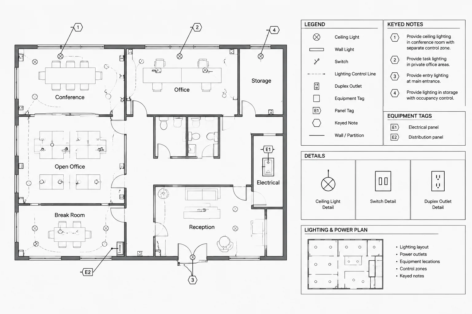
Electrical drawings often need more information than a symbol alone can communicate. A leader may identify a special connection, a callout may direct the reader to an enlarged plan, and a keyed note may describe requirements that would otherwise crowd the drawing. These annotations are useful only when their targets, meanings, and references remain clear.
A consistent workflow for electrical CAD leaders and callouts improves plan readability while reducing ambiguous notes. It also makes later revisions easier because drafters can distinguish project information from disconnected text and improvised linework.
Leaders, callouts, and tags serve different purposes
Although these elements may look similar, they should not be treated as interchangeable.
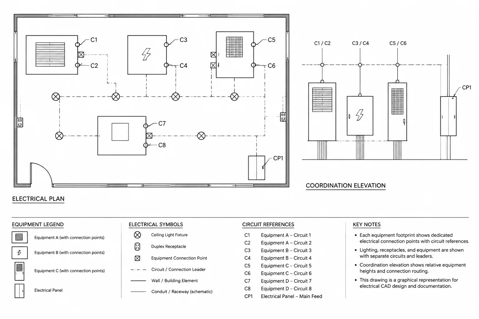
- Leader: Connects a note, label, or identifier to a specific object or location.
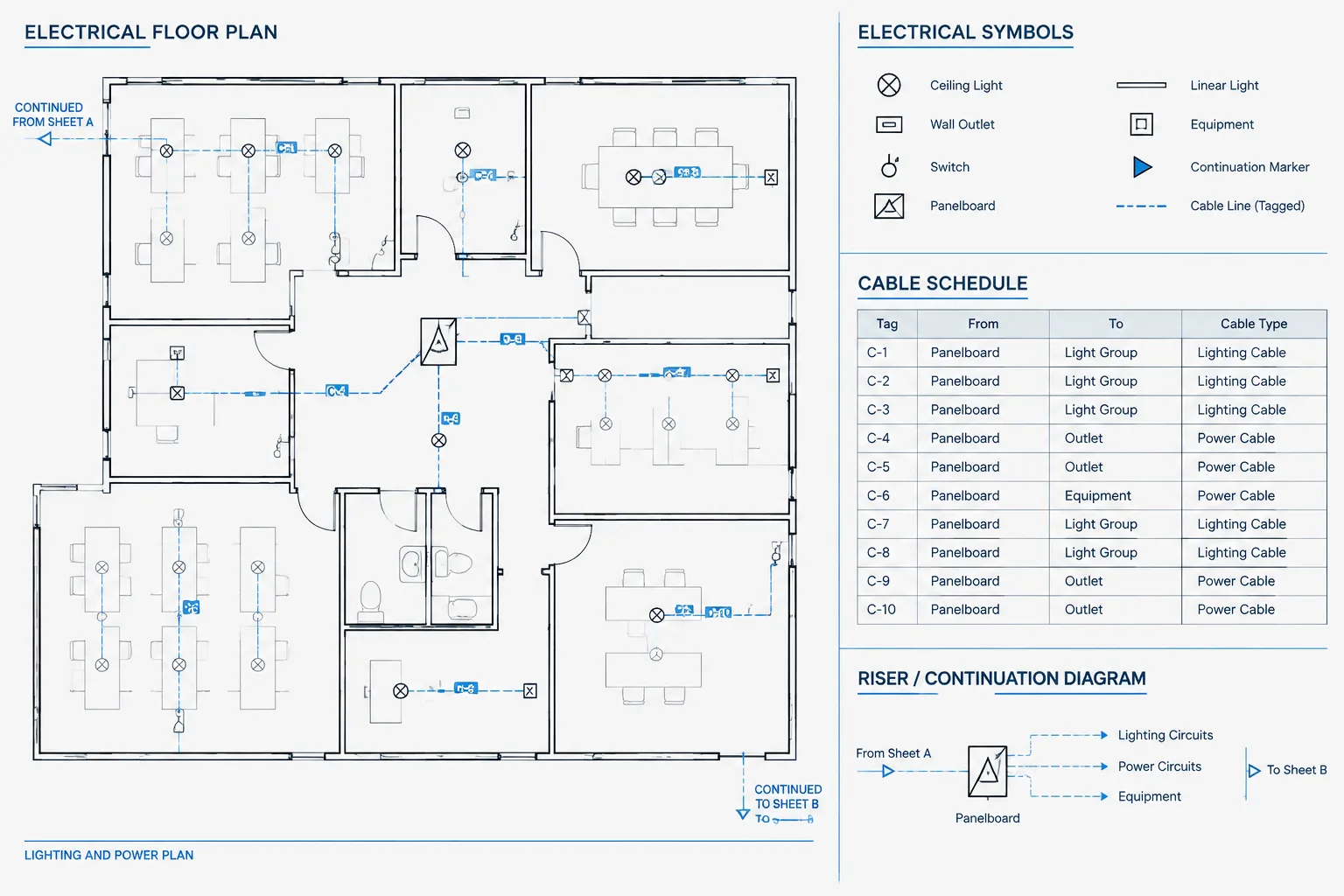
- Keyed-note tag: Links a compact identifier on the plan to an explanatory note list.
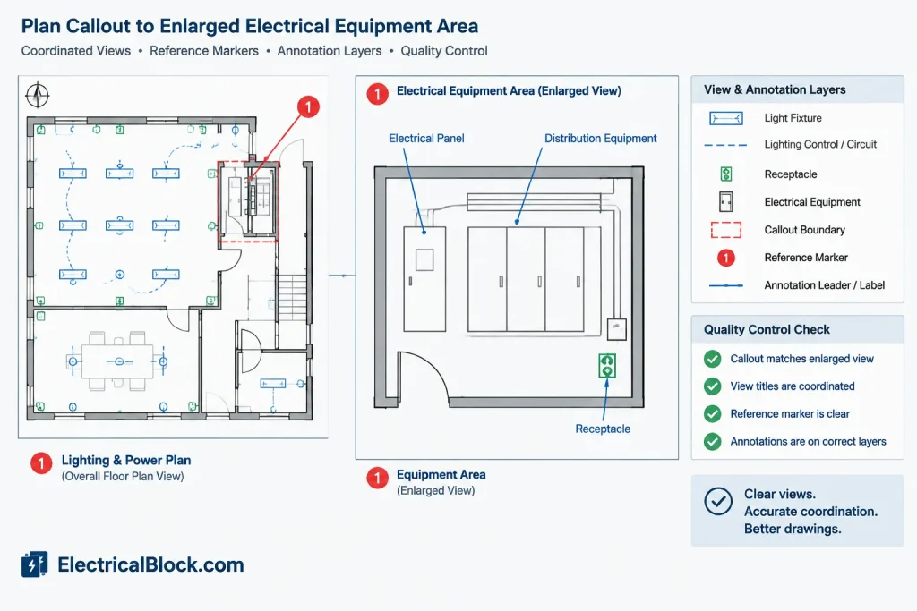
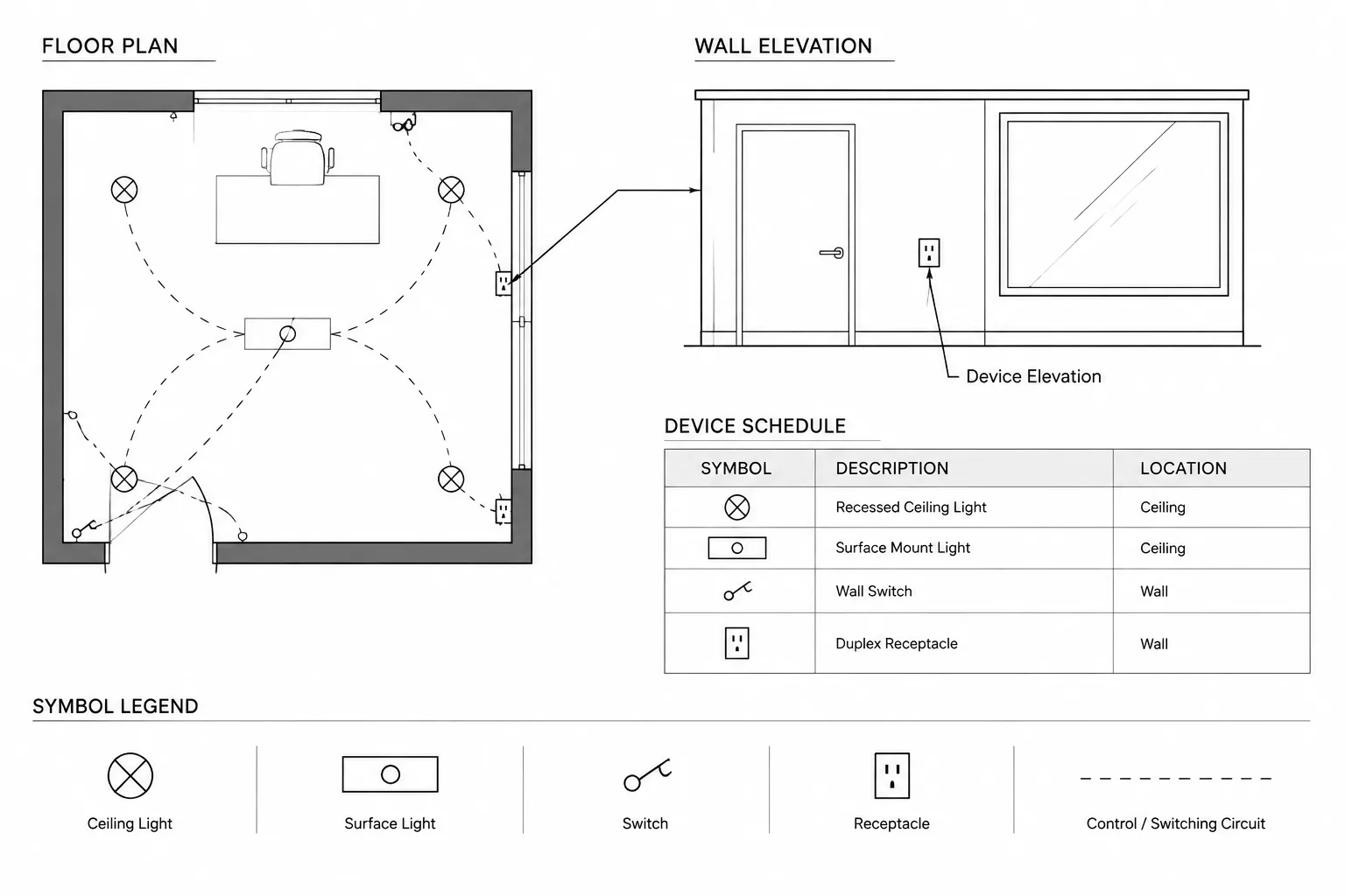
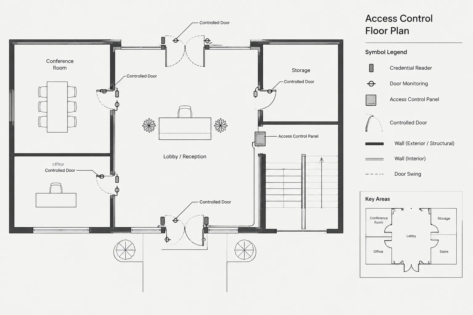
- Detail callout: Directs the reader to a detail, section, elevation, diagram, or enlarged view.
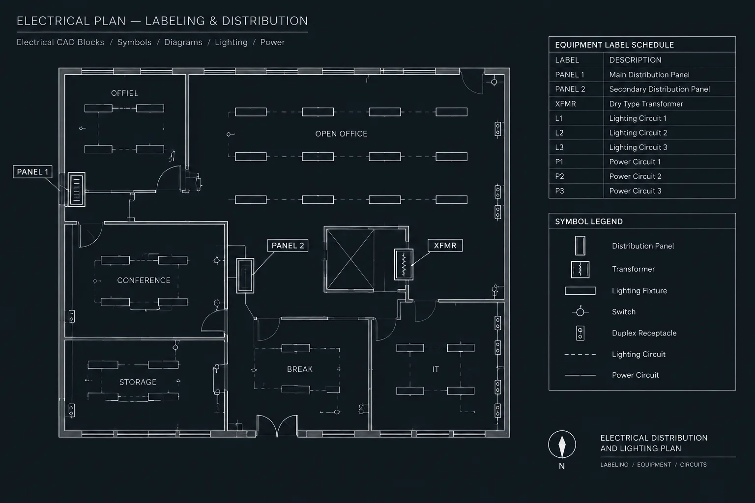
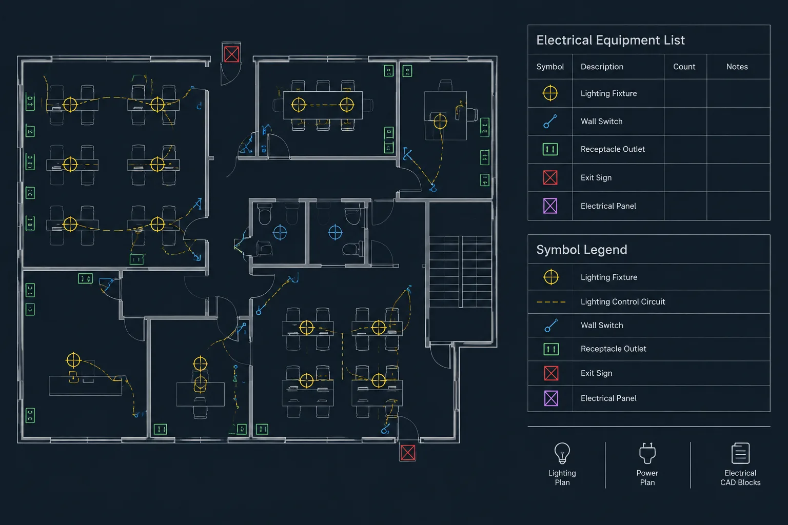
- Equipment or device tag: Identifies an item that may also appear in a schedule, one-line diagram, or equipment list.
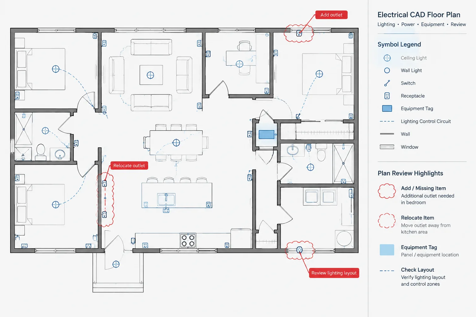
- Area callout: Uses a boundary, cloud, bracket, or similar graphic to identify a region rather than a single object.
Defining these functions in the CAD template helps prevent a common problem: using visually similar bubbles for unrelated information. A reader should be able to recognize whether a marker identifies equipment, opens a note, or points to another drawing view.
Choose the annotation method before placing text
Start by asking what the reader needs to find. A short device identifier may belong beside the symbol without a leader. A condition applying to one object may need a direct leader. Repeated instructions may be better handled by keyed notes. Information requiring another view should use a coordinated reference callout.
This decision matters because excessive leaders can make a plan look like a web of lines. Conversely, a detached note placed near several devices may leave its intended target uncertain. The annotation method should make the relationship explicit without adding unnecessary graphics.
| Documentation need | Useful annotation approach | Primary coordination concern |
|---|---|---|
| Identify one device or equipment item | Adjacent tag or direct leader | Tag must match schedules and diagrams |
| Describe a unique local condition | Leader note | Arrow must terminate at the intended object |
| Repeat the same instruction in several locations | Keyed-note tags and note list | Every tag needs a valid note entry |
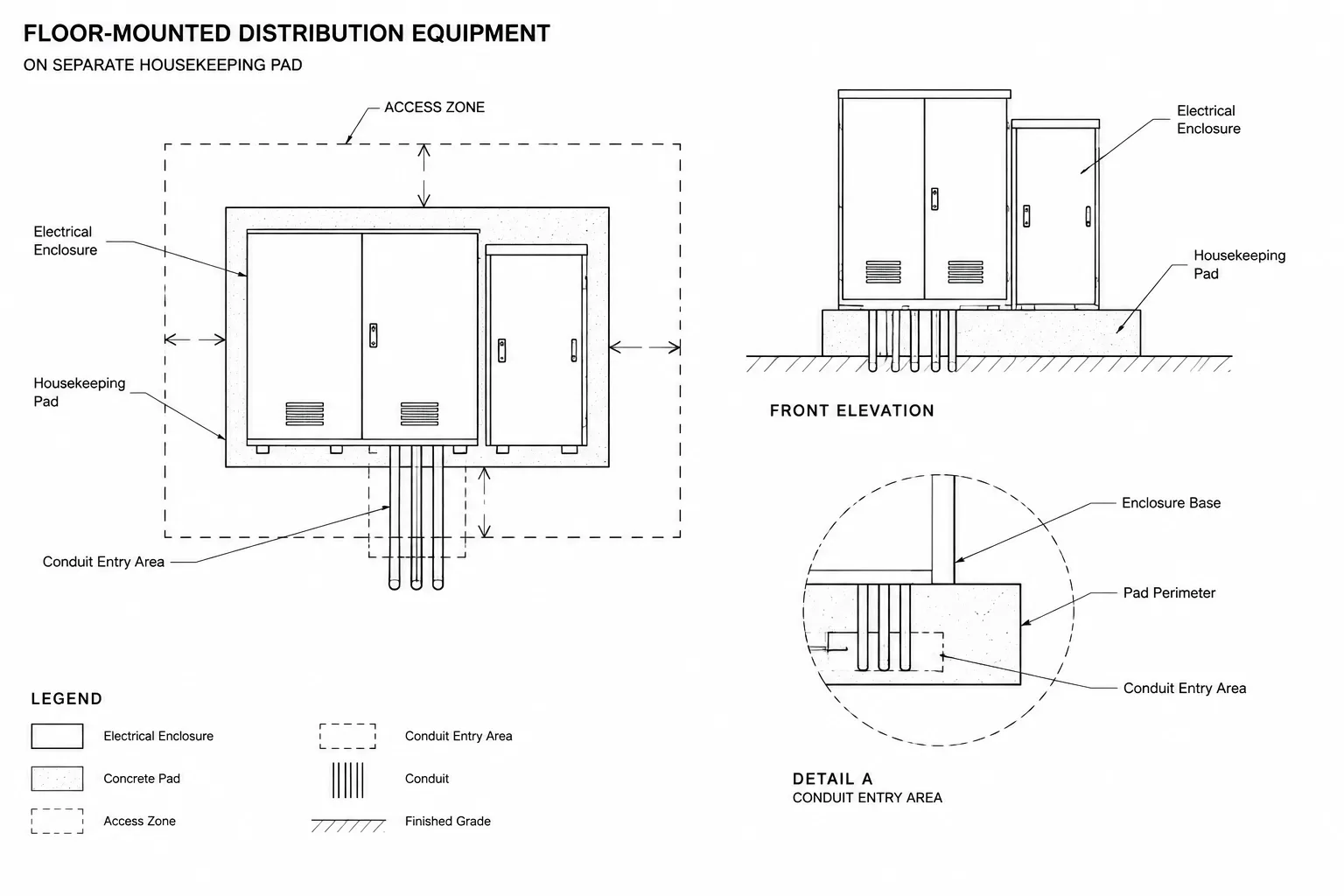
| Refer to a larger or more detailed view | Detail, section, or enlarged-plan callout | View and sheet references must remain current |
| Apply information to a group or region | Boundary or area callout | The included area must be visually unambiguous |
Build a readable leader path
A good leader provides a short, direct visual path from text to target. Route it through open space where practical, avoiding electrical symbols, room names, dimensions, circuiting, and architectural features. A long leader crossing several systems can be mistaken for wiring or another design element.

Use bends deliberately. A landing near the text can organize multiple notes, but repeated bends add visual noise. Keep the arrowhead or endpoint visible against the background. If it disappears into a wall line, hatch, equipment outline, or other dense geometry, adjust the approach angle or move the note.
Leader paths should not depend on color alone. Drawings may be printed in monochrome, reduced, or viewed through software with different display settings. Linetype, lineweight, spacing, and geometry should still communicate the annotation clearly.
Point to the correct graphic target
The leader endpoint should reflect the note’s subject. A note about a device should usually point to the device symbol, while a note about a raceway route should point to the route rather than nearby text. A note addressing an entire assembly may point to its outline or use a bracket that indicates the full scope.
Avoid ending a leader in empty space unless a drafting convention clearly defines that endpoint. Empty-space termination can shift in meaning when backgrounds are updated or nearby items move.
Control text attachment and alignment
Text should attach consistently to its leader so that the relationship remains clear after editing. Maintain a predictable gap between the landing and the text, and avoid placing the landing through letters or underlining text unintentionally.
For stacked notes, use a consistent alignment and reading order. If several leaders originate from one note group, confirm that each path can be followed without crossing another. When the group becomes difficult to trace, separate the notes or replace repeated instructions with keyed notes.
Keep text orientation readable from the established sheet viewing direction. Rotated background geometry does not automatically justify rotating annotations. If a project uses rotated views, establish a project convention and apply it consistently across plans and enlarged views.
Separate annotation from design geometry
Place leaders, callout graphics, and annotation text on deliberate CAD layers rather than on device, circuit, or architectural-background layers. Layer separation supports plotting, review, and selective visibility without changing the underlying design geometry.

The layer structure does not need to be excessively complex. It should, however, allow the project team to distinguish annotation from physical objects. Callout boundaries may also need separation from revision clouds because the two graphics communicate different purposes.
Where a callout combines a bubble, identifier, reference text, and leader, manage it as a coordinated object or block when the CAD workflow supports that approach. Avoid constructing every callout from unrelated lines, circles, and text entities. Loose components are easier to misalign and more likely to become incomplete during revisions.
Coordinate callouts with their destinations
A callout is not complete merely because it looks correct on the source plan. Its destination must exist, carry the expected title or identifier, and show the intended information. References should be checked after views are moved, sheets are renamed, or details are reorganized.
Review both directions where practical. From the plan, confirm that the referenced view can be found. From the detail or enlarged plan, confirm that its title and scope make sense relative to the originating callout. This reciprocal review can expose copied references that still point to an older location.
Do not assume that a callout supplied in a CAD block library is ready for project use. Verify its text fields, layer assignment, scale behavior, linework, and reference format against the current drawing set.
Handle crowded electrical plans without hiding information
In electrical rooms, equipment areas, ceiling plans, and renovation zones, open annotation space may be limited. Moving notes into a clear margin can help, but long crossing leaders may create new ambiguity. Consider an enlarged plan when the base view can no longer show symbols, circuiting, dimensions, and notes legibly.
Background masking can improve readability, but it must be used carefully. An oversized mask may conceal walls, doors, dimensions, or equipment that the reader needs for coordination. Review masked annotations with relevant background layers visible and inspect the plotted output rather than relying only on the editing display.
Do not move a symbol away from its actual documented location merely to create room for a note unless the drawing convention clearly indicates that the symbol is diagrammatic. When location matters, preserve the location and solve the annotation conflict with a leader, offset tag, enlarged view, or revised layout.
Use a focused annotation quality-control pass
Leaders and callouts deserve their own review because they can remain visually plausible even when their information is wrong. A focused check should include:
- Every leader has a visible and intentional target.
- No leader can easily be mistaken for circuiting, wiring, or raceway.
- Callout identifiers match their destination views.
- Keyed-note tags have corresponding note entries.
- Equipment and device tags agree with related schedules and diagrams.
- Text does not overlap symbols, dimensions, or other annotations.
- Masks do not hide required background information.
- Copied callouts do not retain obsolete references.
- Annotation layers plot with the intended hierarchy.
- Leaders remain understandable in the issued sheet scale and format.
Perform this review after major background updates and again when preparing the issue set. Architectural changes can leave a leader pointing at a moved wall, deleted device, or empty location even when the electrical annotation itself was never edited.
Create a small, controlled annotation library
A practical annotation library may include leader-note styles, keyed-note markers, equipment tags, section markers, detail references, and enlarged-plan callouts. Keep the collection limited to graphics with defined purposes. Multiple nearly identical callouts encourage inconsistent use and make training more difficult.
Document the intended function of each annotation type in the CAD standard, template guide, or drawing checklist. Include examples showing what the marker identifies and which related drawings or schedules require coordination. This adds more value than a library of attractive bubbles with no documented workflow.
Clear electrical CAD leaders and callouts are part of the drawing’s information structure, not decorative additions. When their purpose, target, and destination are controlled, they help readers move efficiently between plans, notes, schedules, details, and diagrams without guessing what the drafter intended.

Leave a Reply
You must be logged in to post a comment.