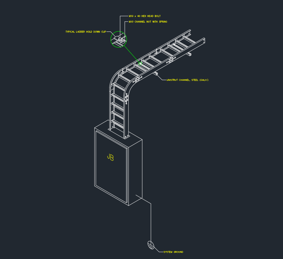
This cable ladder with junction box DWG supports electrical drafting where cable routing and an enclosure connection need to be represented together. The block can help communicate equipment relationships in cable-management plans, routing layouts, coordination drawings, and installation details.
Before incorporating the drawing into project documents, review its geometry, units, scale, layer assignments, and connection points. The CAD block should be adapted to the project drafting standard and checked against the selected equipment and approved design information.
Download our high-quality **cable ladder with junction box DWG file** designed as a detailed CAD Block for professionals. This CAD drawing showcases a precise cable ladder integrated seamlessly with a junction box, perfect for electrical and cable management layouts in commercial and industrial projects. The file is fully compatible with AutoCAD and other popular CAD software, ensuring easy modification and integration into your drafting workflows. Ideal for architects, engineers, and designers, this resource streamlines your project planning, helping you visualize and implement efficient cable routing systems. Enhance your electrical design projects with our accurate, ready-to-use CAD Block today.
Please log in or register to download this file.
What the Cable Ladder and Junction Box Block Represents
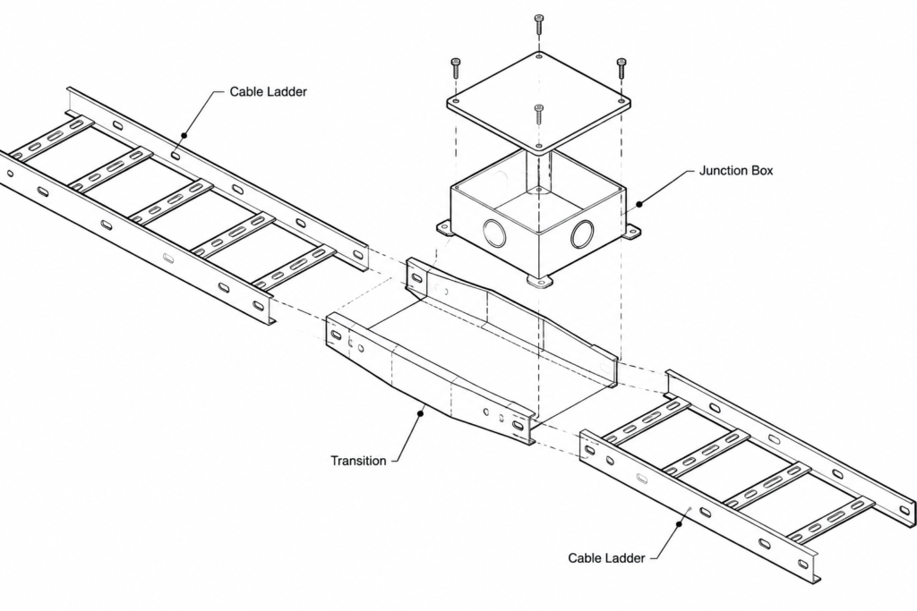
A cable ladder is commonly shown in electrical drawings as a supporting pathway for grouped cables. A junction box represents an enclosure where conductors, cable routes, or related connections may transition, branch, or terminate. Showing these elements together gives the drafter a clear starting point for documenting the relationship between a cable-support system and an enclosure.
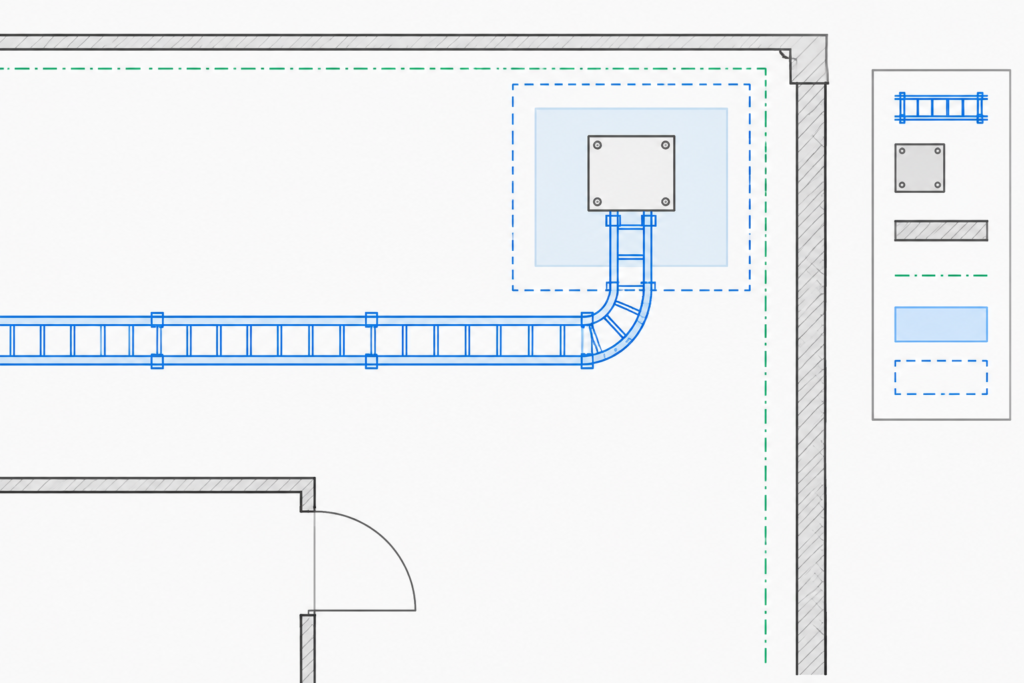
The block is a drafting reference rather than a complete engineered assembly. Actual support conditions, enclosure selection, routing, clearances, fittings, and connection methods must be coordinated with project requirements and verified design documents.
Common Drawing Applications
- Cable-routing plans: Indicate where a ladder pathway approaches or connects with an enclosure.
- Equipment layouts: Coordinate the assembly with walls, structural elements, mechanical services, and adjacent electrical equipment.
- Electrical details: Develop an enlarged or diagrammatic view that clarifies the intended routing relationship.
- Riser and pathway diagrams: Use a simplified representation when documenting cable-system continuity.
- Coordination drawings: Compare the proposed route with other building systems before issuing construction documents.
CAD Placement and Editing Checklist
- Confirm the drawing units and insertion scale before placing the block.
- Inspect the block definition for unnecessary nested geometry, duplicate linework, or unrelated layers.
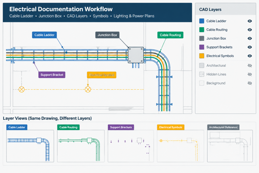
- Place the ladder, enclosure, centerlines, hidden features, and annotations on appropriate project layers.
- Use a consistent insertion point and orientation so repeated instances remain easy to align.
- Check that lineweights and linetypes remain legible at the intended plotted scale.
- Add project-specific tags, route identifiers, enclosure references, and notes outside the reusable geometry when practical.
- Coordinate the block with the project legend, cable schedule, equipment schedule, and related detail callouts.
Documentation and Coordination Considerations
The graphic should communicate more than physical proximity. Where the design requires it, annotations can distinguish the cable route, identify the enclosure, and direct the reader to related schedules or details. Avoid relying on the block alone to define construction requirements that belong in specifications, approved equipment data, or engineered details.
For a consistent drawing set, compare this block with related cable tray CAD blocks, junction box symbols, conduit-routing details, electrical legends, and equipment-layout references. These topic relationships help readers move between the physical layout, diagrammatic representation, and annotation system used across the project.
Quality Checks Before Issuing a Drawing
Review the completed layout for clashes, disconnected geometry, ambiguous route changes, and overlapping labels. Confirm that the junction box location is coordinated with the represented cable pathway and that the drawing does not imply an unsupported connection. Final dimensions, access requirements, supports, fittings, and installation conditions should come from verified project information rather than assumptions based on a generic CAD block.
Frequently Asked Questions
What is included in a cable ladder with junction box DWG?
It is CAD linework representing a cable ladder in relation to a junction box. Open the file and inspect the available geometry, views, layers, and block structure before using it in a project drawing.
Can the block be used directly in an electrical plan?
It can be inserted as a drafting reference, but its units, scale, orientation, layers, and graphic conventions should first be matched to the destination drawing. Project-specific equipment and installation details also require verification.
Should the junction box be shown on a plan, detail, or diagram?
The appropriate representation depends on the drawing purpose. A plan emphasizes physical location, a detail clarifies the routing relationship, and a diagram communicates system continuity without necessarily showing exact placement.
How should this CAD block be annotated?
Use the project naming convention for enclosure tags, cable-route identifiers, detail references, and notes. Keep annotation readable and coordinate it with legends and schedules rather than embedding unsupported technical information in the block.
What should be checked after editing the DWG?
Check units, scale, insertion point, layer mapping, linetypes, lineweights, text style, plot appearance, and coordination with nearby systems. Also confirm that modifications have not created duplicate or disconnected linework.


Leave a Reply
You must be logged in to post a comment.