
I/O wiring diagrams in CAD connect physical field wiring with control-system documentation. Their value depends less on graphical complexity than on whether each signal can be followed through device tags, cables, terminals, interfaces, channels, and related drawings.
The following reference explains how to organize that information without confusing physical connection points with logical control identifiers. It is intended for drafting, drawing coordination, and document review rather than control-system design or field installation.
I/O wiring diagrams document how field devices connect to the input and output channels of a control system. They sit between several other project documents: control schematics explain functional intent, panel layouts show physical equipment, terminal drawings organize connection points, and cable schedules track conductors between locations.
Because these documents share so much information, an I/O drawing can become difficult to maintain if it is treated as an isolated schematic. A practical CAD workflow should make each signal traceable from the field device to the terminal, cable, control panel, channel, and related control function without overcrowding the sheet.
This guide focuses on drafting and documentation. Actual control-system design, equipment selection, terminations, testing, and installation require project-specific engineering and verification.
What an I/O wiring diagram should communicate
An effective I/O diagram answers a sequence of documentation questions:
- What field device produces or receives the signal?
- What signal or control function is being represented?
- Which cable and conductors carry the connection?
- Does the route pass through a junction box, marshalling enclosure, or terminal strip?
- Which control-panel terminal receives the connection?
- Which input or output channel is associated with it?
- Where can the reader find related details, layouts, schedules, or logic documentation?
The diagram does not need to reproduce every fact from every related document. It should show enough information to establish continuity and provide clear references to the documents that contain the remaining data.
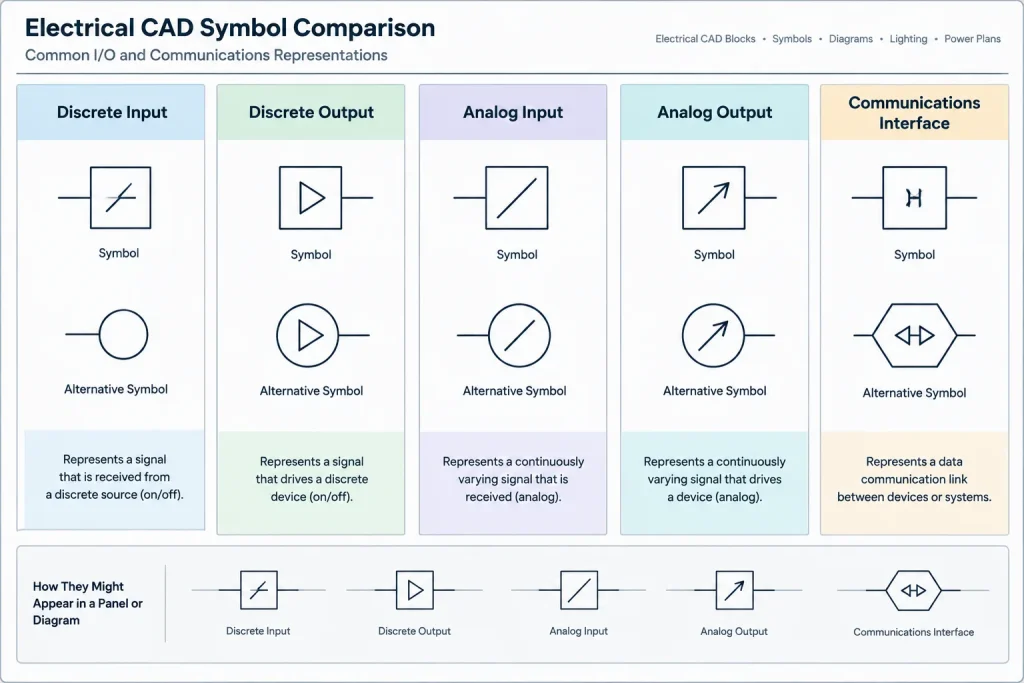
Common I/O categories
I/O points are often grouped by the type of information exchanged with the control system. The exact terminology and hardware arrangement vary by project, but common categories include:
| Category | Typical drawing purpose | Common documentation concern |
|---|---|---|
| Discrete input | Shows a field status or contact condition received by the control system | Contact state, source device, and channel reference must be unambiguous |
| Discrete output | Shows a control command sent to a relay, starter interface, indicator, or other device | Interposing devices and external power sources should not be hidden |
| Analog input | Shows a measured process or equipment signal entering the control system | Signal conductors, shielding documentation, and associated terminals require coordination |
| Analog output | Shows a variable command sent from the control system to a field or equipment interface | The controlled device and signal destination should match schedules and control documentation |
| Communications interface | References a networked or serial data connection rather than an individual hardwired point | The diagram should distinguish communications links from conventional I/O conductors |
These categories should not be assumed from line appearance alone. Use labels, consistent symbols, and a legend so that a reader does not have to infer the signal type from color or linetype.
Build a traceable signal path
A useful diagram follows the signal path in a predictable direction. Depending on the project convention, the field device may appear on one side of the sheet and the control system on the other. Consistency matters more than the chosen direction.
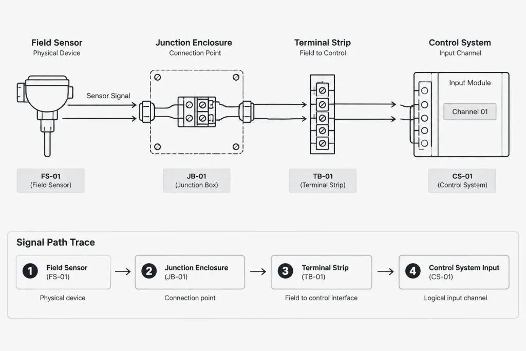
A typical documentation path may include:
- Field-device tag and description
- Device connection or terminal designation
- Cable identification
- Conductor or pair identification
- Intermediate enclosure and terminal reference
- Control-panel terminal reference
- I/O module or interface designation
- Channel identifier or logical address
- Cross-reference to the associated schematic or control function
Not every signal passes through all of these stages. Direct connections and packaged-equipment interfaces may use a shorter path. Show only the stages that actually exist, but avoid graphical shortcuts that make intermediate connection points disappear.
Separate physical and logical identifiers
One of the most common sources of drawing confusion is the mixing of physical terminal data with logical control-system data. A terminal number identifies a connection point. A channel designation identifies a hardware input or output location. A logical address or software tag identifies how the control system refers to the point. These identifiers may be related, but they are not interchangeable.
Use distinct attribute fields or annotation locations for each data type. For example, an I/O channel block might include separate fields for:
- Panel or enclosure
- Module or interface tag
- Channel reference
- Logical point name
- Signal description
- Terminal reference
- Drawing cross-reference
This structure makes later revisions safer. A logical point name can change without forcing the drafter to rebuild the terminal graphics, while a revised panel arrangement can be documented without losing the functional description.
Use CAD blocks without turning the drawing into a database dump
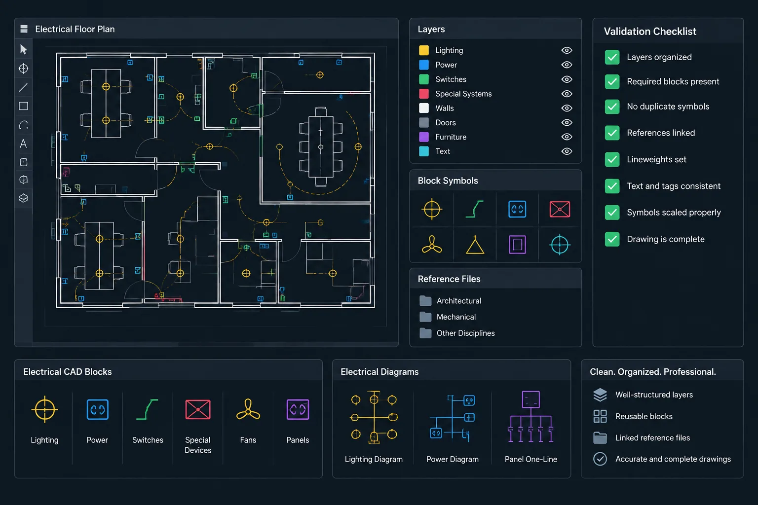
Attributed CAD blocks can help standardize channel symbols, field devices, terminal points, and cross-reference markers. The visible portion of a block should present the information needed to read the sheet. Additional properties can support extraction or checking, but displaying every attribute usually makes the diagram harder to use.
Useful block families may include:
- Field-device connection symbols
- Discrete and analog channel symbols
- Terminal and connector symbols
- Shield and drain-wire references
- Continuation and off-sheet reference symbols
- Junction box or marshalling references
- Packaged-equipment interface symbols
Keep graphical symbols separate from project data where practical. The symbol defines how an item looks; attributes define which specific item it represents. Avoid exploding blocks simply to edit a tag, because that removes the consistency and extraction benefits of the block definition.
Coordinate terminals, cables, and conductors
Connection continuity is easier to review when cable and terminal information is placed close to the associated linework. However, repeating too much information can create conflicts between drawings.
Establish a project rule for the authoritative location of each data type. The I/O diagram might show cable and conductor IDs while the cable schedule remains the source for route, origin, destination, and descriptive data. Likewise, the diagram may show terminal references while the terminal plan or strip schedule remains the source for jumper and spare-terminal arrangements.
When an intermediate junction or marshalling point exists, show both sides of the connection. A cable entering an enclosure and another cable leaving it should not appear as one uninterrupted cable unless that representation accurately reflects the project documentation.
Show cross-references as part of the circuit
Cross-references should be treated as essential signal-path data rather than optional notes. A reader may need to move between an I/O diagram, control schematic, panel layout, terminal schedule, equipment plan, and cable schedule to understand one connection.
A clear cross-reference identifies the destination drawing and, where the drawing system supports it, the relevant detail, zone, rung, or location. Use the same reference format throughout the set. If a continuation symbol appears at both ends of a connection, the references should form a matching pair.
Do not use an off-sheet connector to conceal unresolved linework. It should indicate a real continuation with a defined destination.
Plan layers for editing and review
Layer organization should support visibility control without fragmenting one signal across too many categories. A practical I/O drawing may separate:
- Device and channel symbols
- Connection linework
- Terminal graphics
- Cable and conductor labels
- Cross-references
- General notes and headings
- Background or enclosure outlines
- Revision and review markup
Signal categories can also be separated when the project requires filtered views, but line color should not be the only means of communicating meaning. Drawings must remain understandable when printed monochrome or viewed with alternate plot settings.

Choose a sheet organization method
Large I/O sets can be organized by control panel, equipment system, process area, signal type, or functional group. Each approach has tradeoffs.
Panel-based sheets make hardware and terminal coordination easier. Equipment-based sheets help readers find all points associated with a machine or packaged system. Signal-type sheets can simplify repeated channel graphics but may separate related control functions. Select one primary organization method and use indexes or cross-references to support the others.
Avoid changing organization methods midway through the drawing set. If exceptions are necessary, explain them in the drawing index or general notes.
Quality-control checks before issue
An I/O drawing review should compare more than graphics. A structured check can include:
- Every channel shown on the diagram has a unique and readable identifier.
- Field-device tags agree with plans, equipment documents, and control schematics.
- Cable and conductor IDs match the cable documentation.
- Terminal references exist and point to the correct enclosure or strip.
- Input and output classifications are consistent across drawings and schedules.
- Intermediate relays, isolators, converters, and packaged interfaces are not omitted.
- Shield and drain-wire notation agrees with the project documentation approach.
- Off-sheet connectors and continuation references form complete pairs.
- Unused, spare, future, and removed points are clearly distinguished.
- Extracted I/O lists do not contain duplicate or blank identifiers.
Automated attribute extraction can help locate missing fields and duplicate tags, but it cannot confirm whether the documented connection is technically correct. Visual review and coordination with the responsible design information remain necessary.
Keep the I/O diagram maintainable
The best I/O wiring diagrams are not merely complete at the first issue. They are structured so that later changes can be incorporated without breaking references throughout the set. Reusable symbols, separate identifier fields, controlled layer use, and clearly assigned sources of truth all reduce revision risk.
Before adopting a CAD block or sample diagram, verify its terminology, attributes, signal conventions, and graphic behavior against the project requirements. A generic block can provide a useful drafting starting point, but it does not establish the correct control architecture, terminal assignment, or field connection for a real installation.
A documentation workflow for coordinated I/O drawings
Before drafting individual connections, define which project document controls each type of information. Device tags may originate in an equipment list, cable identifiers in a cable schedule, terminal assignments in terminal documentation, and logical point names in control-system records. The CAD drawing should reference these sources consistently rather than becoming an independent copy of every project dataset.
Establish the drawing data structure
Separate visible annotations from data used for checking or extraction. Information needed to trace the signal should remain readable on the sheet, while supporting properties can stay within block attributes. Consistent attribute names make it easier to compare drawings, detect incomplete records, and update repeated symbols.
Draft the signal path
Place connection stages in the project’s established reading direction. Preserve each real boundary between the field device and the control interface, including terminals, intermediate enclosures, and packaged-equipment interfaces. Continuation symbols should identify where the path resumes rather than substitute for unresolved documentation.
Review relationships, not only linework
A visually complete circuit can still contain conflicting data. Reviewers should compare the field tag, cable reference, conductor designation, terminal location, channel classification, logical point name, and drawing reference as a coordinated record. Any change to one item should trigger a review of the documents that repeat or depend on it.
Prepare the drawing for revision
Maintainable drawings use reusable blocks, stable layer assignments, separate attribute fields, and predictable cross-reference formats. Revision clouds or markup layers can identify changed areas during review, but the final record should also reflect the revised identifiers in every associated schedule and drawing.
An I/O diagram should therefore be evaluated as part of a documentation system. Clear symbols matter, but reliable coordination between drawings is what allows a reader to trace and verify the represented connection.
Frequently asked questions
What is the difference between an I/O wiring diagram and a control schematic?
An I/O wiring diagram emphasizes connection continuity between field devices, terminals, cables, interfaces, and control-system channels. A control schematic emphasizes functional relationships and operating intent. Projects may use both because neither drawing necessarily contains all physical and logical information.
Should terminal references and channel references use the same label?
No. A terminal reference identifies a physical connection point, while a channel reference identifies an input or output location in the control system. Keeping them in separate fields prevents one identifier from being mistaken for the other.
How much block attribute data should appear on the sheet?
Show the attributes needed to read and trace the connection. Supporting properties used for extraction, filtering, or quality checks can remain hidden when displaying them would overcrowd the drawing. The project’s documentation rules should determine which data remains visible.
How should communications interfaces appear on an I/O drawing?
Use symbols, labels, and line conventions that distinguish a communications link from individual hardwired conductors. The drawing should identify the connected equipment and direct the reader to the documentation containing the network or interface details.
What should be checked after an I/O point is revised?
Review every document that shares the changed information, including relevant schematics, terminal records, cable schedules, equipment drawings, panel documentation, and control-system records. Also verify that continuation markers and cross-references still lead to the correct destinations.
Can a generic CAD block define the correct field connection?
No. A generic block can standardize graphics and attribute locations, but it cannot determine the correct device connection, terminal assignment, channel selection, or control architecture. Those decisions require verified project information and responsible engineering review.







Leave a Reply
You must be logged in to post a comment.