
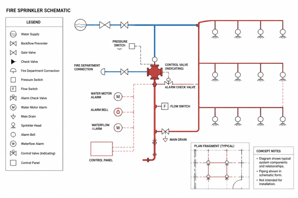
A fire sprinkler system schematic diagram is a coordination tool that represents the relationships between water-supply components, control equipment, distribution piping, and sprinkler coverage areas. Unlike a floor plan, a schematic emphasizes functional connections and system flow rather than exact physical routing.
For CAD and MEP documentation, the drawing can help architects, engineers, and designers review equipment relationships before detailed plans are coordinated. It should be treated as a reference drawing and reviewed against the project design, equipment requirements, architectural conditions, and applicable engineering criteria before use.
Discover a high-quality Schematic Diagram For Sprinkler System available as a DWG file and CAD Block, perfect for architects, engineers, and designers. This detailed schematic diagram provides a clear representation of sprinkler system layouts, ensuring efficient fire safety planning for residential, commercial, or industrial projects. The DWG file is fully compatible with AutoCAD and other leading CAD software, making it easy to edit and integrate into your existing designs. Ideal for professionals seeking accurate, ready-to-use sprinkler system schematics for construction documentation and MEP coordination. Download now to streamline your design workflow and enhance project precision.
Please log in or register to download this file.
What a fire sprinkler schematic shows
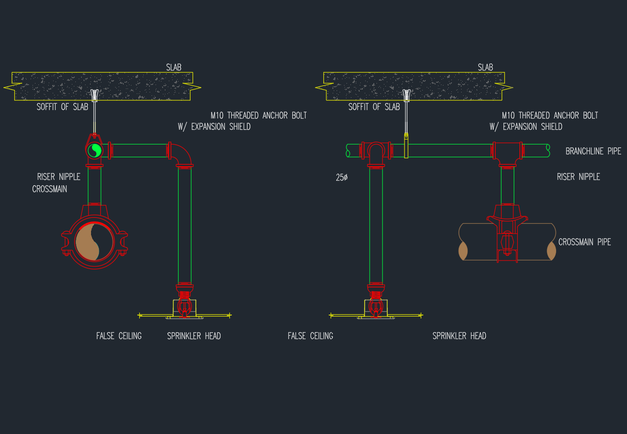
A schematic commonly organizes the principal parts of a sprinkler arrangement into a readable sequence. Depending on the drawing, this may include the incoming water connection, control or sectional equipment, alarm-related components, riser or main piping, branch piping, and sprinkler locations. The diagram is intended to make the relationship between these elements easier to understand than a congested plan view.
How to read the diagram
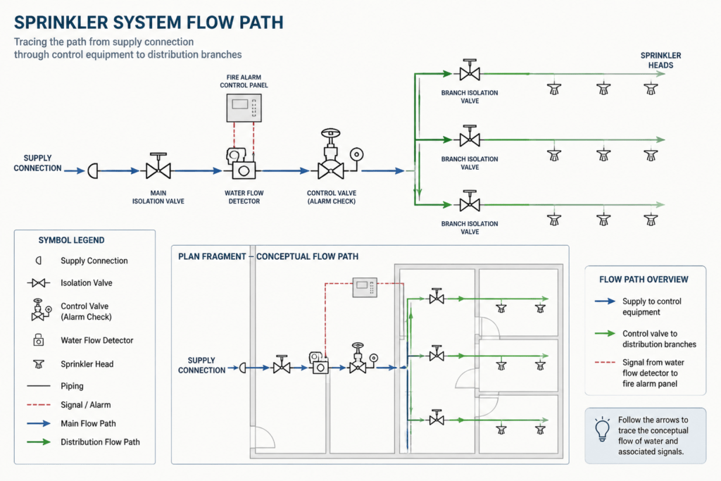
Begin with the system source and follow the connected piping toward the distribution branches. Then identify the symbols or labels used for valves, supervisory or alarm devices, drains, test connections, and sprinklers. The legend is important because graphical conventions can vary between drawing packages and CAD libraries.
- Flow path: Trace the connected piping from the supply side toward the areas served.
- Control points: Look for devices that isolate, monitor, test, or drain portions of the system.
- Distribution: Distinguish primary piping from branch piping and terminal sprinkler locations.
- Notes and callouts: Review them for design intent, coordination information, or references to other drawings.
Using the DWG in MEP coordination
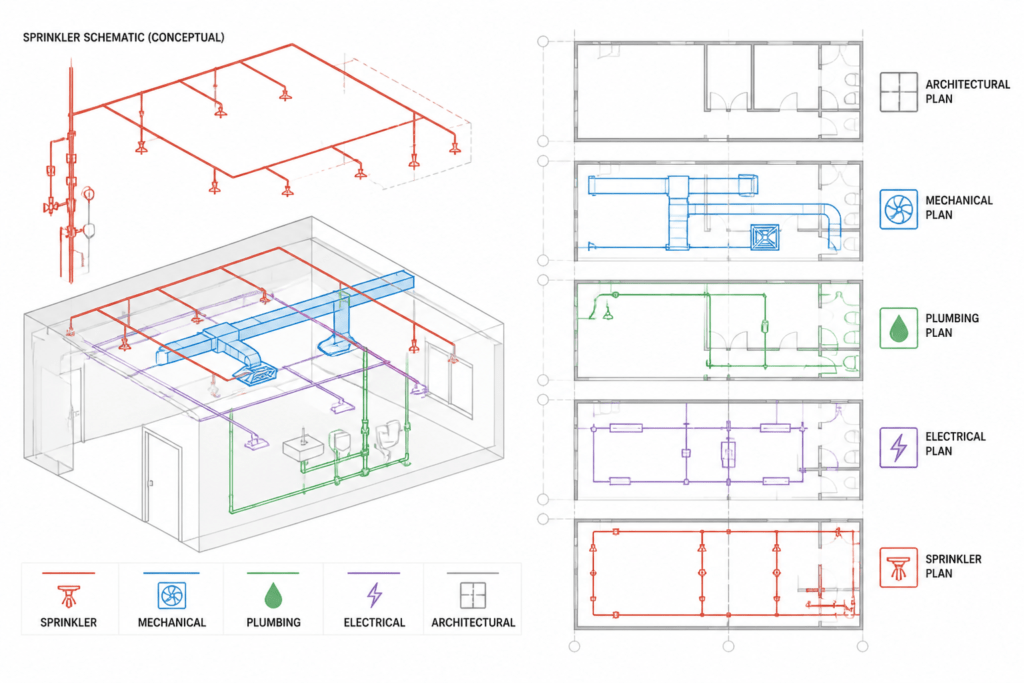
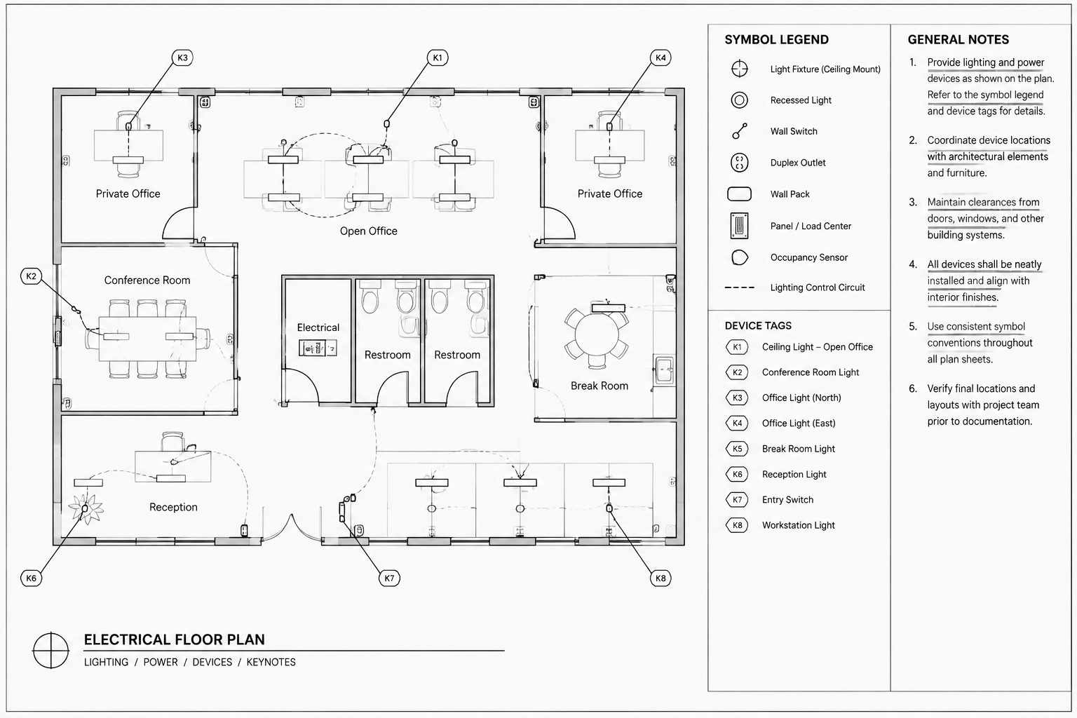
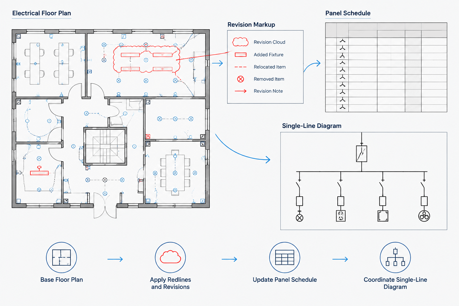
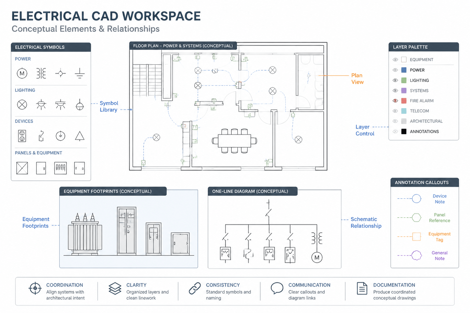
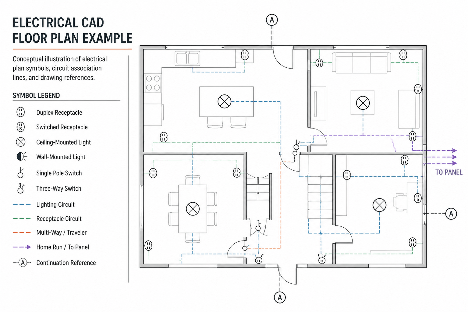
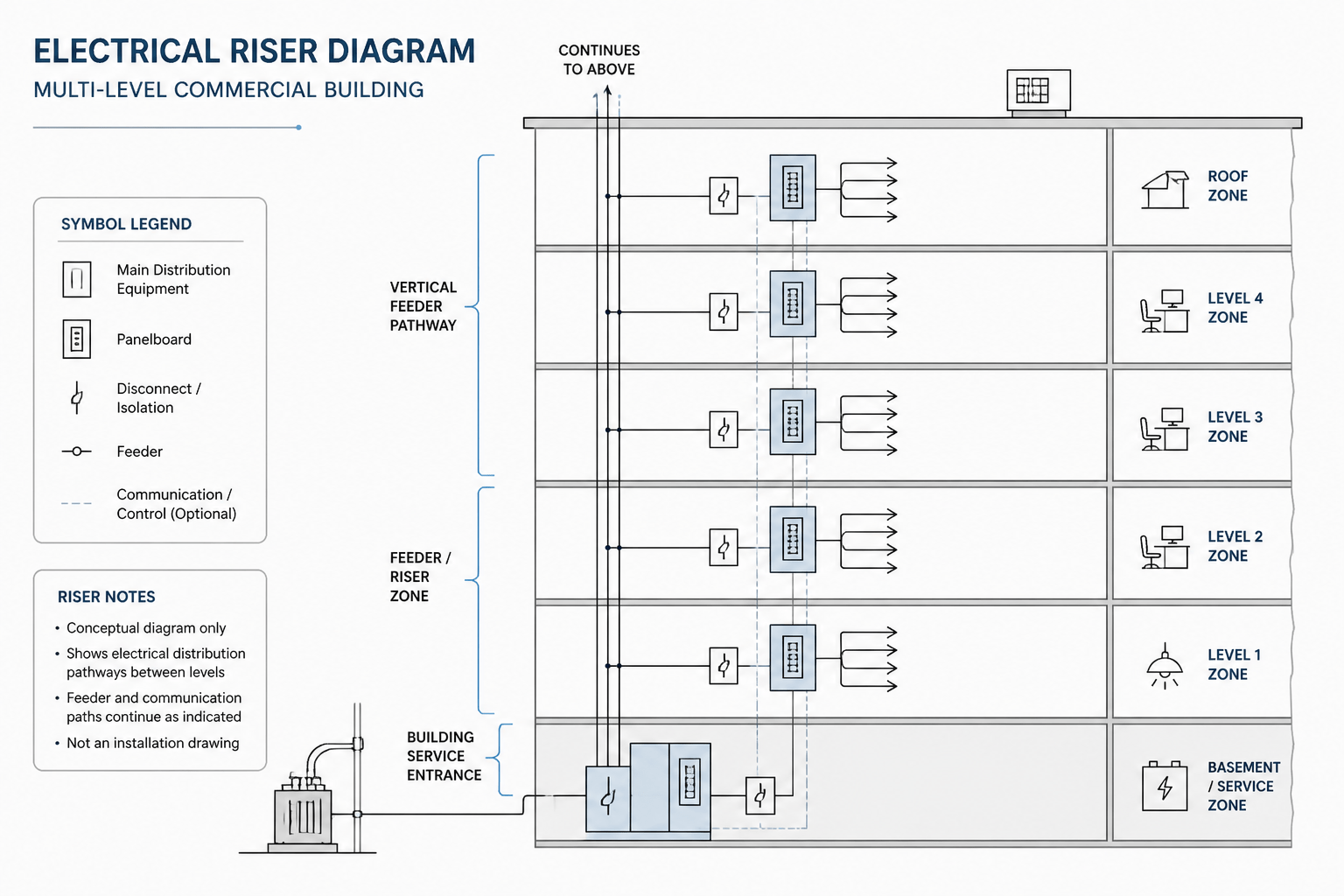
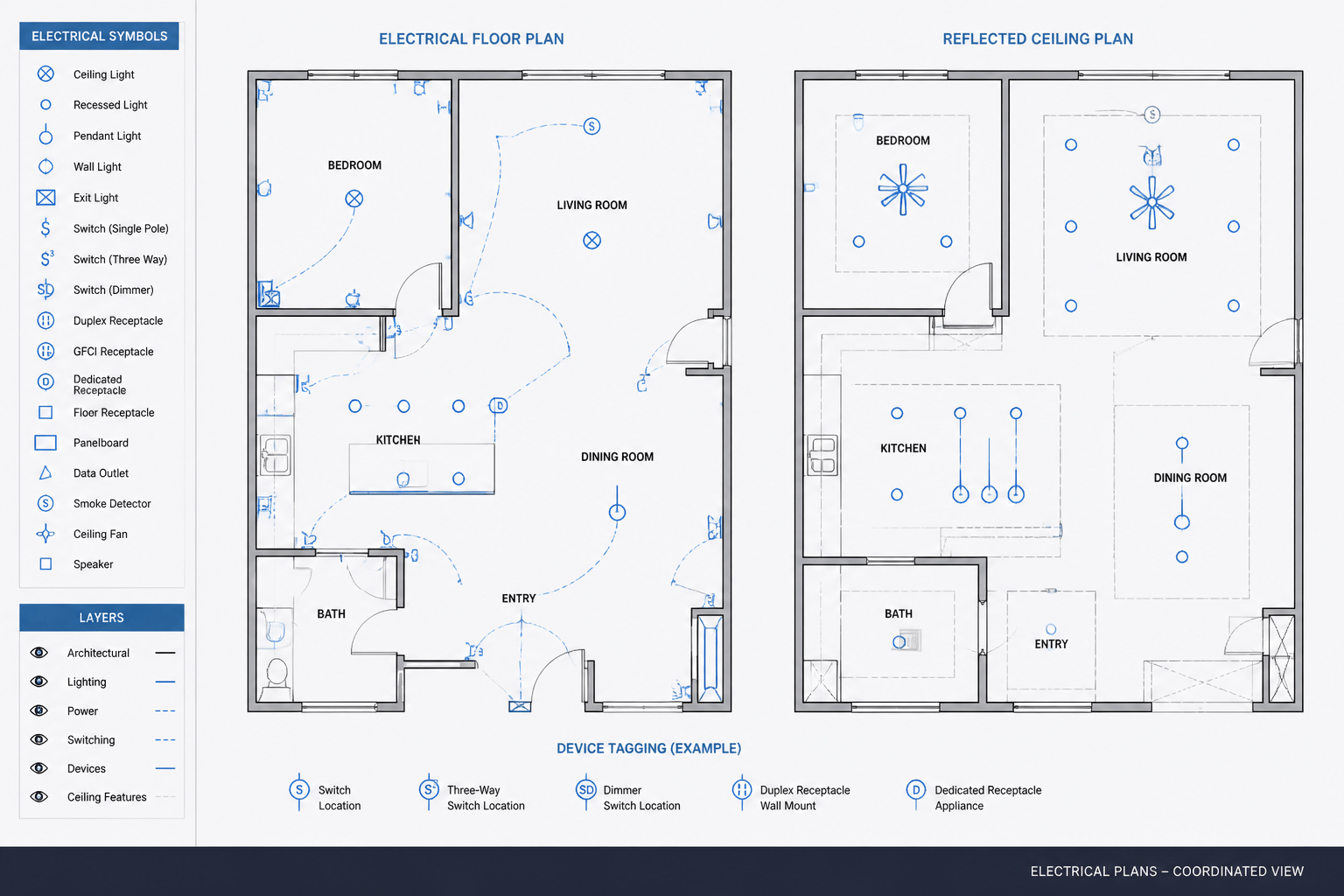
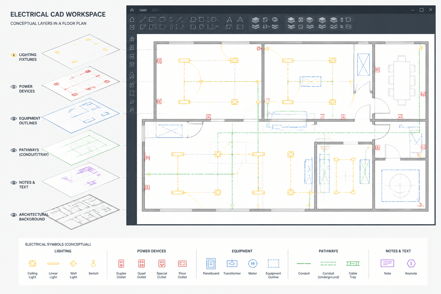
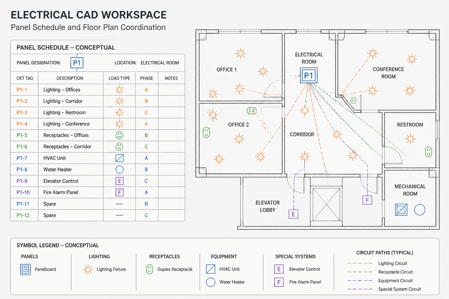
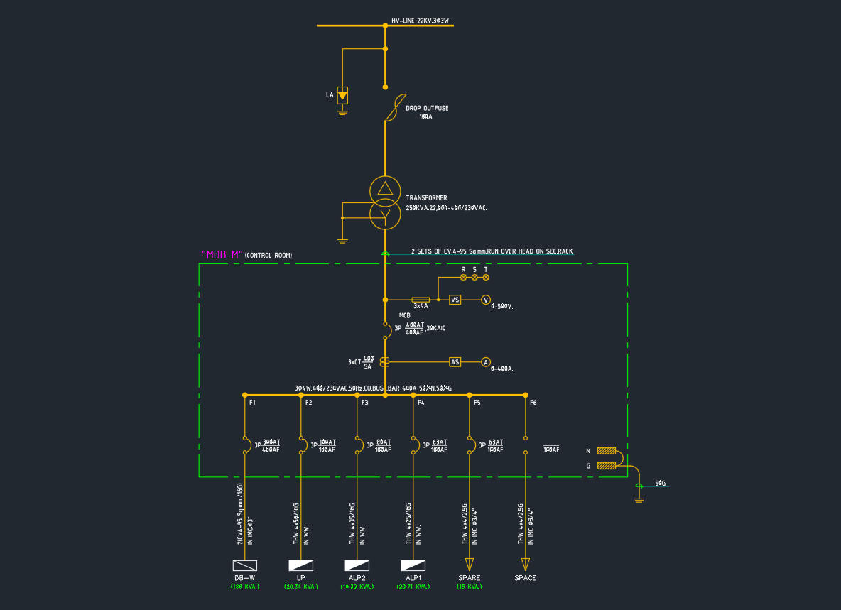
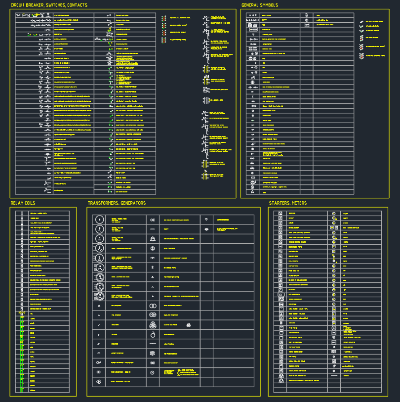
When the schematic is incorporated into a CAD workflow, keep equipment, piping, annotation, and reference information organized on clearly named layers. Use consistent linework and symbol conventions so the sprinkler information can be reviewed alongside architectural, plumbing, mechanical, and electrical drawings. In a coordinated set, electrical references may show relationships to alarm or supervisory equipment, while the sprinkler schematic remains focused on the water-based system arrangement.
A schematic is not a substitute for a project-specific hydraulic design, coordinated installation drawing, or professional review. Verify the source drawing, symbols, equipment relationships, and site conditions before relying on it for construction documentation.
Reference checklist
- Confirm that the drawing legend is available and understandable.
- Check that supply, control, distribution, and terminal components are visually distinguishable.
- Compare schematic intent with the related floor plans and equipment layouts.
- Coordinate clearances, penetrations, ceiling conditions, and access requirements with the project team.
- Have the final design reviewed by the responsible qualified professionals.
Frequently asked questions
What is a fire sprinkler system schematic diagram?
It is a simplified drawing that explains how the main components of a sprinkler system are connected and how water is distributed through the system. It emphasizes system relationships rather than exact installation geometry.
Is a sprinkler schematic the same as a sprinkler floor plan?
No. A schematic focuses on functional connections and equipment sequence, while a floor plan shows the system in relation to rooms, walls, ceilings, architectural features, and physical routing.
What should I check before using a sprinkler DWG?
Review the symbol legend, layer organization, labels, piping relationships, and drawing coordination. Confirm that the reference matches the project requirements and has been reviewed by the responsible design professionals.
Can the schematic be used as an installation-ready design?
Not by itself. A reference schematic does not replace project-specific calculations, coordinated drawings, equipment information, or professional verification.
Why is MEP coordination important for sprinkler drawings?
Sprinkler piping and equipment share building space with architectural, mechanical, plumbing, and electrical systems. Early coordination helps identify conflicts and keeps related drawings consistent.
Leave a Reply
You must be logged in to post a comment.