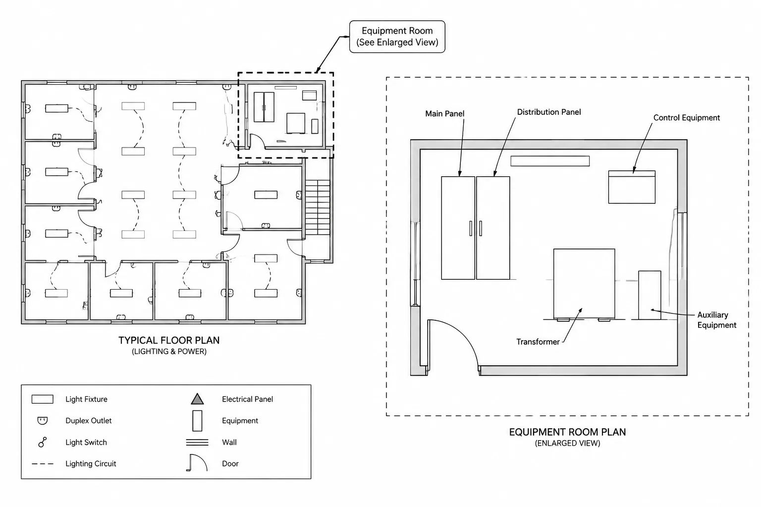
Enlarged electrical plans are most effective when they improve legibility without creating a separate version of the design. The key drafting challenge is not simply making an area appear larger; it is maintaining a dependable relationship among the parent plan, shared geometry, local annotation, and every reference that guides the reader between views.
This guide explains how to define enlargement boundaries, coordinate callouts and titles, assign information ownership, manage viewport visibility, and review both views as connected parts of the electrical drawing set.
Enlarged electrical plans provide a closer view of areas that cannot be documented clearly at the scale of the main floor plan. Electrical rooms, equipment clusters, service areas, control stations, and other coordination-intensive spaces often need more room for device tags, dimensions, circuit information, and references.
An enlarged plan should not become an independent drawing that conflicts with the overall plan. It is a coordinated view of the same design information, presented at a scale that supports clearer documentation. A reliable CAD workflow therefore needs to address source geometry, view limits, annotation ownership, callout references, and revision control.
When an enlarged electrical plan is useful
Enlargement is appropriate when the main plan cannot show the required information without crowding, ambiguous leaders, or excessive symbol displacement. The decision should be based on documentation needs rather than on the physical size of the room alone.
Common candidates include:
- Electrical rooms with panels, transformers, switchboards, disconnects, or control equipment.
- Mechanical spaces containing several pieces of electrically connected equipment.
- Service entrances and utility interface areas.
- Equipment alcoves where access zones and connection points must be coordinated.
- Areas with dense receptacle, control, communications, or specialty-system layouts.
- Locations requiring plan dimensions, equipment tags, and references to multiple details.
An enlarged plan may also be useful where the main plan intentionally presents only routing or system context. The enlargement can then show local arrangement and identification without forcing every note onto the overall floor plan.
Define the purpose before creating the view
Before drawing a boundary or creating a viewport, identify what the enlarged plan must communicate. Possible purposes include equipment arrangement, branch-circuit documentation, feeder routing, connection-point coordination, mounting relationships, or access-zone review.
A view without a defined purpose often accumulates unrelated information. It may become a second floor plan with duplicate notes, inconsistent tags, and no clear documentation priority. A short internal description such as “equipment arrangement and connection coordination” helps the CAD team decide what belongs in the view.
Choose a source-geometry strategy
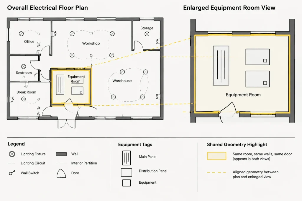
The safest workflow generally keeps physical design geometry in one controlled location. An enlarged plan can then display that geometry through a viewport, referenced file, or other managed view method. The exact method depends on the project CAD environment, but the principle is consistent: avoid maintaining two manually edited versions of the same equipment layout.
| Approach | Advantage | Primary risk |
|---|---|---|
| Viewport of shared model geometry | Plan changes appear in both overall and enlarged views | View-specific layer and annotation control must be managed carefully |
| Referenced enlarged-plan file | Useful for separating work areas or discipline responsibilities | Reference paths, coordinates, and update timing require control |
| Copied geometry | Quick to establish for a limited drafting task | Copies can diverge and create conflicting project information |
Copied geometry should be treated cautiously. If duplication is unavoidable, define which view controls the design and establish a review step that compares the duplicate against its source before every issue.
Draw a meaningful view boundary
The enlargement boundary on the parent plan tells the reader what area is represented elsewhere. It should enclose enough context to make the relationship obvious without capturing unrelated portions of the building.
Include recognizable architectural features where practical, such as walls, doors, columns, shafts, or room limits. These features help users orient themselves when moving between sheets. Avoid boundaries that cut directly through important equipment or split a coordinated assembly unless the division is intentional and clearly referenced.
The boundary graphic should remain distinguishable from electrical circuiting, raceway routes, demolition limits, and revision clouds. Its layer, linetype, and plotting treatment should support that distinction. The project legend or drawing conventions should explain any boundary style that is not self-evident.
Coordinate the callout and destination title
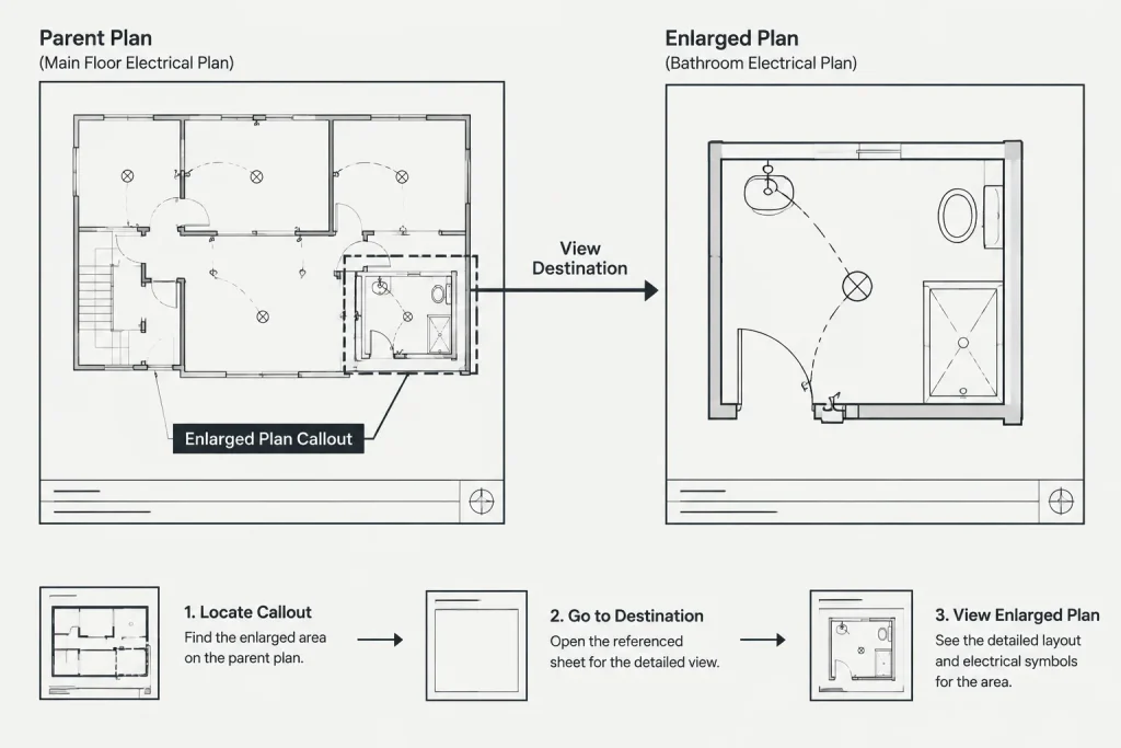
The parent-plan callout and the enlarged-view title form a two-way navigation pair. A reader should be able to find the enlarged plan from the overall plan and understand where the enlargement came from when viewing it independently.
A coordinated reference typically identifies:
- The destination view or detail identifier.
- The destination sheet, when the enlargement is placed on another sheet.
- A descriptive view title based on the room, area, or function.
- The presentation scale or a clearly stated not-to-scale condition, as applicable.
Use the same area name in the callout, view title, room label, and related schedule references. Small wording differences can create doubt about whether two labels describe the same location. If architectural room names or numbers change, include enlarged-plan titles in the coordination review.
Separate model information from view-specific annotation
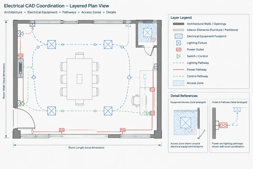
Physical objects such as equipment footprints, walls, devices, and major pathways may be shared between the main plan and enlargement. Annotation often needs more deliberate ownership.
Text sized for an overall plan may be too small, too dense, or poorly positioned in an enlarged view. Conversely, large view-specific notes can overwhelm the parent plan if they are visible everywhere. Use the project’s established annotation and viewport controls to determine where each label appears.
Information commonly shared between views
- Equipment and device locations.
- Room geometry and fixed architectural references.
- Primary raceway or cable-tray paths.
- Equipment identification that must remain consistent throughout the set.
Information commonly managed for the enlarged view
- Detailed dimensions and alignment references.
- Closely spaced leaders and local notes.
- Access or service-zone graphics.
- Connection-point callouts.
- References to elevations, sections, and installation details.
View-specific annotation should clarify shared geometry, not redefine it. For example, an equipment tag in the enlargement should match the identifier used on the one-line diagram and schedule rather than introducing a local alternative.
Control what remains visible on the parent plan
Creating an enlarged plan does not automatically justify removing all information from the parent plan. The overall view still needs enough content to communicate system continuity and spatial relationships.
The parent plan may retain equipment symbols, key identifiers, feeder or branch-circuit context, and the enlargement callout. Dense dimensions, detailed connection notes, and overlapping leaders can be moved to the enlarged view. When information is intentionally omitted, a concise reference can direct the reader to the enlargement.
Avoid leaving the parent area visually empty. A blank space inside an enlargement boundary can make it difficult to understand routing, scope, or the relationship to adjacent rooms.
Coordinate dimensions and reference points
Dimensions on an enlarged electrical plan should support coordination rather than merely fill available space. Dimension to stable architectural or structural references when those references are appropriate for the project. Clearly distinguish dimensions that locate equipment from dimensions that describe equipment or clearance graphics.
Do not assume that a downloaded CAD block represents a verified product footprint, connection location, or access requirement. Generic blocks are useful for drafting and early coordination, but project documentation should be checked against current project criteria and verified manufacturer information where product-specific geometry matters.
If dimensions appear in more than one view, determine which view governs and review both after changes. Uncontrolled duplicate dimensions are especially vulnerable to revision conflicts.
Manage layers and viewport visibility intentionally
An enlarged view often needs a different visibility balance than the overall plan. Architectural backgrounds may require additional detail, while unrelated electrical systems may need to be screened or hidden. Establish a repeatable layer-visibility method rather than freezing layers individually without documentation.
Check that the enlargement displays:
- The background features required for orientation and dimensioning.
- All equipment and devices within the stated view scope.
- Relevant connection and pathway information.
- Callouts that point to valid details, sections, or diagrams.
- No unintended annotations from adjacent areas or other plan types.
Layer changes should be reviewed in both the enlargement and parent plan. Hiding a layer to clean one view can accidentally remove essential information elsewhere if visibility controls are not view-specific.
A practical enlarged-plan workflow
- Identify the documentation problem. Determine why the main plan is insufficient and what the enlargement must resolve.
- Select the source method. Use shared geometry or a controlled reference wherever practical.
- Set the view limits. Include enough surrounding context for orientation.
- Create the parent callout. Place it where it does not resemble circuiting or obscure devices.
- Title the enlarged view. Match project room and area terminology.
- Configure visibility. Display only the systems and background information needed for the view’s purpose.
- Add local annotation. Place dimensions, notes, leaders, and secondary references at a readable density.
- Coordinate related documents. Compare identifiers with schedules, one-lines, elevations, and equipment lists.
- Review both directions. Confirm that the parent plan leads to the correct enlargement and that the enlargement can be traced back to its source area.
Common enlarged-plan errors
- Independent redraws: The enlarged layout changes while the overall plan remains unchanged.
- Mismatched area names: The room title, callout, and schedule use different terminology.
- Missing system context: Equipment is shown locally, but incoming or outgoing connections cannot be followed.
- Duplicate conflicting notes: Similar instructions appear in both views with different wording.
- Unclear governing dimensions: The same location is dimensioned differently on separate sheets.
- Overcropped backgrounds: The reader cannot identify where the enlarged area sits within the building.
- Unverified block geometry: Generic symbols are treated as exact equipment footprints.
Final quality-control review
Review an enlarged electrical plan as part of the complete drawing set, not as an isolated detail. Confirm that every callout reaches a valid destination, view titles match the parent plan, identifiers agree with schedules and diagrams, and shared geometry has not been duplicated unnecessarily.
Plot or export the sheet during review. On-screen clarity does not guarantee readable linework, text hierarchy, or background contrast in the issued document. A well-coordinated enlargement should reduce ambiguity while preserving a clear relationship to the overall electrical plan.
Establish information ownership before sheet production
A simple ownership plan can prevent conflicting edits. For each information type, decide whether it belongs to the shared model, the parent plan, the enlarged view, or a coordinated schedule or diagram. The goal is to give every item a clear controlling location while allowing other views to reference it.
- Shared design geometry: Maintain equipment, devices, architectural references, and major pathways in the controlled source used by both plan views.
- Parent-plan context: Retain the information needed to understand system continuity, adjacent spaces, routing, and the location of the enlargement.
- Enlarged-view annotation: Place detailed dimensions, local leaders, connection notes, and close coordination references where they remain readable.
- External coordination data: Check identifiers against schedules, diagrams, equipment lists, elevations, and other documents that control related information.
Use a change-impact review
Whenever the enlarged area changes, review more than the visible equipment arrangement. A relocated device or revised room boundary may affect the parent-plan callout, viewport crop, dimensions, leaders, pathway graphics, sheet references, and related schedules.
A practical review starts with the source geometry and follows the information outward. Confirm that the parent view still provides adequate context, the enlargement displays the intended area, and all references lead to current destinations. This approach treats the enlargement as part of a coordinated documentation system rather than as an isolated sheet graphic.
Distinguish design conflicts from presentation conflicts
Not every discrepancy has the same cause. A design conflict occurs when views show different equipment, locations, identifiers, or connections. A presentation conflict occurs when the underlying design is consistent but annotation, visibility, cropping, or linework causes the views to communicate it differently.
This distinction helps the CAD team select the correct response. Design conflicts require correction at the controlling source. Presentation conflicts are generally resolved through view settings, annotation placement, callout coordination, or plotting adjustments. Both should be checked before issue because either type can mislead the drawing user.
Frequently asked questions
What is the difference between an enlarged plan and an electrical detail?
An enlarged plan usually presents a larger-scale plan view of an area while preserving its relationship to the overall floor plan. A detail may isolate a specific condition, assembly, connection, or installation concept and may not reproduce the full plan context.
Should the overall plan and enlargement use the same geometry?
Shared, controlled geometry is generally preferable because changes can appear in both views. If geometry is copied, the drawing team should identify the governing source and include comparison of the copies in the revision process.
How much context should an enlargement boundary include?
The boundary should include enough recognizable background information to orient the reader and coordinate the documented work. It should avoid unnecessary adjacent areas while not cutting through important equipment or hiding the relationship to surrounding spaces.
Which annotations should remain only in the enlarged view?
Detailed dimensions, closely spaced leaders, local connection notes, access graphics, and secondary detail references are common candidates. Equipment identifiers and other coordinated data should remain consistent with the parent plan, schedules, and diagrams.
What should happen if the parent plan and enlargement conflict?
Do not assume that the larger view automatically governs. Determine which drawing location controls the affected information, correct the source, and review every dependent view and reference for the same issue.
Can a generic CAD block define the final equipment footprint?
A generic block can support layout studies and drawing organization, but it should not be treated as verified product geometry. Where exact geometry affects documentation, compare the drawing with current project criteria and verified manufacturer information.




Leave a Reply
You must be logged in to post a comment.