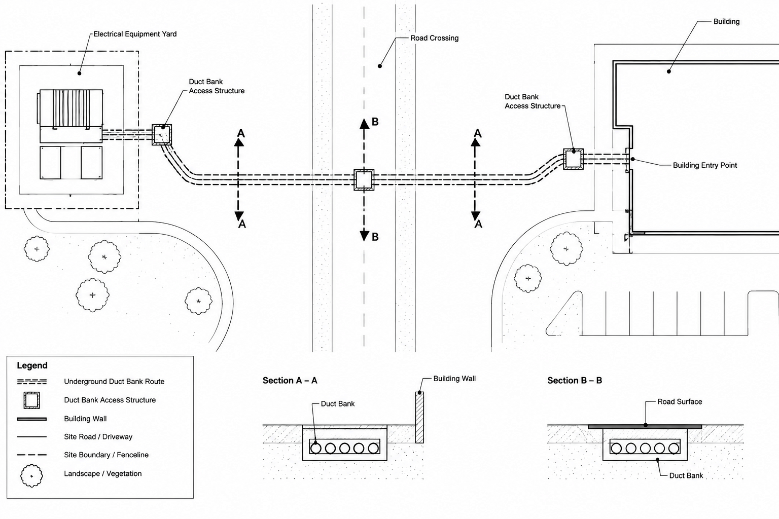
An underground electrical duct bank CAD drawing must communicate more than a route between two points. It should show where the underground system runs, what it connects to, how its elevation changes, and where it interacts with buildings, roads, utilities, foundations, and site features.
Clear documentation usually requires several coordinated views rather than one heavily annotated plan. A site plan establishes the horizontal route, a profile explains vertical conditions, and sections or details clarify the conduit arrangement. Schedules, tags, and notes then connect those views into a usable drawing package.
This guide focuses on drafting and drawing coordination. Actual conduit configurations, burial conditions, separation requirements, structural design, and installation criteria must be determined by the responsible project professionals and verified against applicable project requirements.
What an Underground Duct Bank Drawing Should Communicate
A complete drawing package should allow a reviewer to answer several basic questions:
- Where does the route begin and end?
- Which equipment, structure, or building entry does it serve?
- What systems occupy the route?
- Where does the route change direction or elevation?
- Which utility crossings or physical conflicts require coordination?
- Where are pull structures, vaults, handholes, or similar access points located?
- Which section or detail defines the physical arrangement?
The drawings do not need to repeat every piece of information in every view. They do need reliable references so that a reader can move between the plan, profile, sections, schedules, and related disciplines without guessing.
Build the Drawing from Coordinated Views
Route Plan
The route plan is the primary horizontal view. It normally uses a coordinated civil, survey, architectural, or site background and shows the duct bank in relation to permanent site features.
Useful plan information may include:
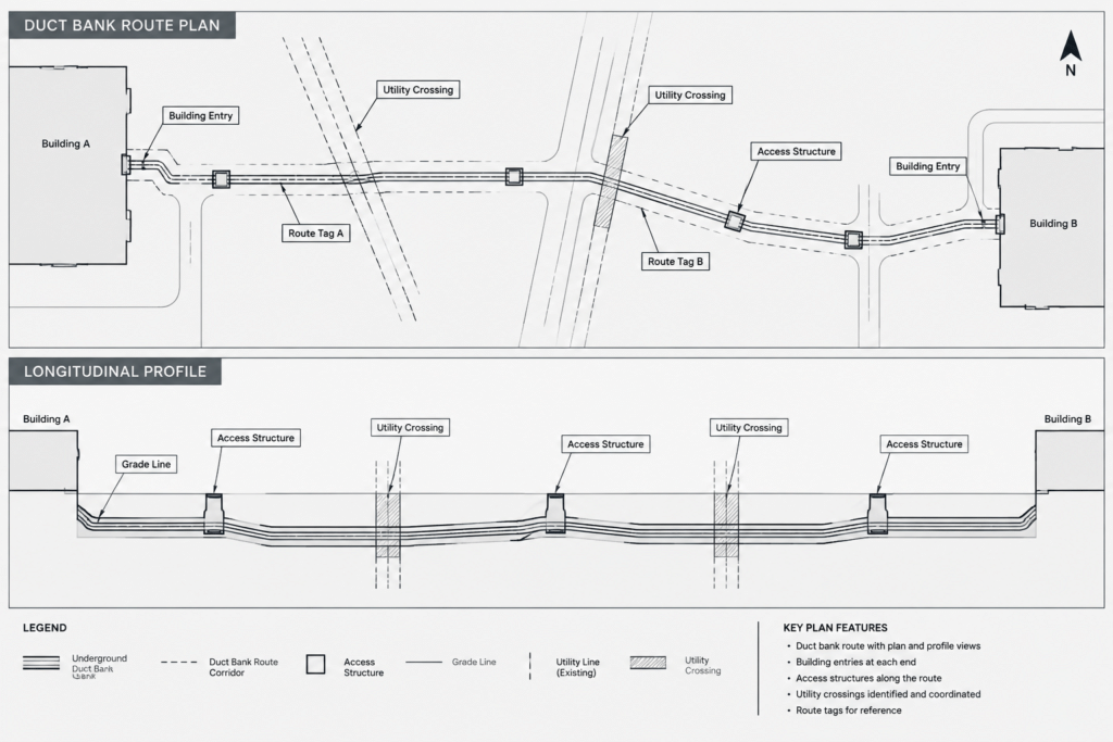
- Duct bank route and directional changes
- Equipment pads, electrical rooms, and building entry points
- Pull structures and access structures
- Roads, curbs, sidewalks, walls, and property features relevant to coordination
- Known utility crossings
- Route segment tags
- Section cuts and profile references
- Continuation references where the route crosses sheet boundaries
Avoid drawing the route as an unexplained pair of parallel lines. Its graphic representation should match the legend and remain distinguishable from other underground utilities. Where several electrical systems share a corridor, use tags or keyed linework to identify design intent without overcrowding the plan.
Route Profile
A profile presents the vertical relationship between the proposed route and surrounding conditions. It is especially useful where the route passes beneath roads, drainage features, existing utilities, structural elements, or changing grades.
A profile may identify existing and proposed grade lines, structure locations, building interfaces, utility crossings, and changes in route elevation. Horizontal and vertical information should use the project’s established datum and coordinate references. If the profile uses different presentation scales in each direction, label that condition clearly so readers do not interpret the geometry literally.
Do not add assumed elevations simply to make the profile appear complete. Missing design information should be flagged for coordination rather than converted into unsupported CAD data.
Sections and Details
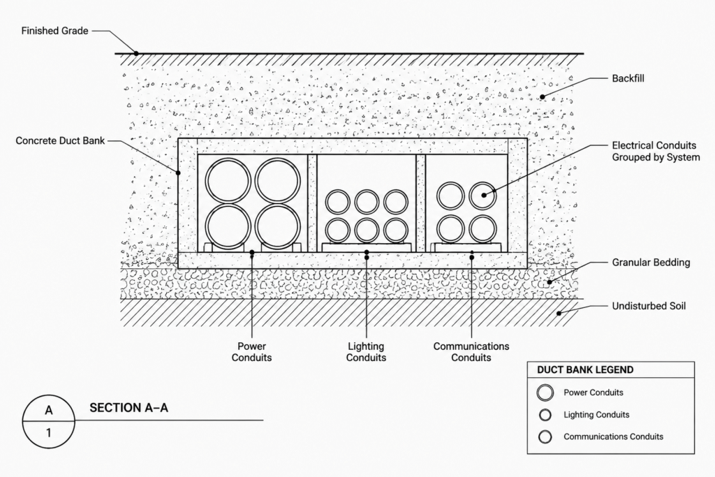
Sections explain the physical arrangement that the route line cannot show. Depending on project needs, a section can distinguish conduits by system, identify spare positions, show grouping intent, and reference surrounding construction.
Use a typical section only where conditions are genuinely typical. A route passing through a wall, under a structural feature, or near another utility may require a location-specific section. The plan should make clear where each special section applies.
Create a Route Segmentation System
Dividing the route into tagged segments makes a complex underground system easier to document. A segment can represent the run between two structures, between a structure and equipment, or between defined changes in condition.
A practical segment schedule can contain the following fields:
| Field | Purpose |
|---|---|
| Segment ID | Provides a unique reference used on plans, profiles, and schedules. |
| From | Identifies the originating equipment, structure, or location. |
| To | Identifies the destination equipment, structure, or location. |
| System or service | Describes the documented electrical function without relying only on color. |
| Configuration reference | Points to the applicable section, detail, or project-defined type. |
| Routing remarks | Records special crossings, transitions, or coordination notes. |
Segment IDs should remain stable as the design develops. Renaming every downstream segment after inserting a new run can create avoidable revision errors. A nonsequential but unique identifier is often easier to manage than forcing continuous numbering after every change.
Represent Structures and Connection Points Clearly
Vaults, handholes, pull boxes, and similar structures need consistent symbols and unique tags. The symbol should show the structure’s location and orientation where orientation affects conduit entry. A separate schedule or detail can carry information that would otherwise clutter the site plan.
For each structure, coordinate:
- The tag shown in plan and profile
- The structure type or detail reference
- Conduit entry directions
- Associated route segment IDs
- Relevant elevation references
- Ownership or scope boundaries, when applicable
Building and equipment connections also need explicit endpoints. A route should not disappear beneath a building outline without a continuation note, entry detail, or reference to the interior electrical plan.
Use Layers to Separate Meaning
An underground electrical plan often combines proposed work, existing conditions, demolition, survey information, and multiple utility systems. Separate these categories through a controlled layer structure rather than changing individual object properties.
Useful layer groups may distinguish:
- Proposed duct bank routes
- Existing underground electrical work
- Structures and access points
- Route tags and annotations
- Profile geometry
- Section graphics
- Utility crossings
- Reference backgrounds
- Removal or abandonment information
Layer names should follow the project’s CAD standard. Color, linetype, and lineweight should reinforce status and system identity, but critical distinctions should not depend on color alone. The issued drawing must remain understandable in its intended plot format.
Coordinate Crossings and Congested Areas
Utility crossings are common sources of drawing conflicts. The electrical route plan should be compared with current civil, structural, plumbing, fire protection, communications, and landscape information as applicable to the project.
At each important crossing, verify that the drawings identify the crossing location and provide enough information for design review. A crossing identifier can connect the route plan to a profile or enlarged section. Where the available background does not confirm an existing utility’s position, use appropriately qualified notation instead of presenting uncertain information as exact.
Congested areas may need enlarged plans. Enlargements are useful near building entries, utility yards, groups of structures, and routes passing through constrained corridors. Match lines and view references should connect the enlargement back to the overall plan.
Coordinate the Plan, Profile, and Schedule
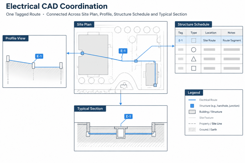
The same route must tell the same story in every view. If a structure appears in plan, confirm that it appears in the profile and relevant schedule. If a segment changes type, confirm that the change location is identified consistently. If a route is revised, check every section marker, continuation reference, and endpoint tag affected by that revision.
A simple coordination matrix can help during quality control:
| Drawing Element | Check Against |
|---|---|
| Route segment | Plan, profile, segment schedule, and section reference |
| Access structure | Plan symbol, profile location, structure schedule, and detail |
| Building entry | Site plan, entry detail, interior plan, and equipment location |
| Utility crossing | Plan location, profile or section, and coordination note |
| Sheet continuation | Match line, destination sheet, and repeated endpoint information |
Common Drafting Problems to Avoid
- Unreferenced route lines: Every route should have identifiable endpoints and a documented purpose.
- Conflicting tags: Structure and segment IDs must match across all views.
- Unsupported elevations: Do not infer design values from incomplete backgrounds.
- Overloaded plans: Move configuration data into schedules, profiles, or sections when plan readability suffers.
- Ambiguous crossings: Use enlarged views or profile references where simple line crossings do not explain vertical relationships.
- Detached typical details: A detail is useful only when the drawings identify where it applies.
- Outdated backgrounds: Record and review the reference files used for coordination before issue.
Pre-Issue CAD Review Checklist
- Confirm that all routes have clear origins and destinations.
- Check segment and structure tags for duplicates or omissions.
- Verify plan, profile, section, and schedule references.
- Review building entries and equipment interfaces.
- Inspect utility crossings and constrained areas.
- Confirm that proposed, existing, and removal work remain visually distinct.
- Check match lines and continuation notes between sheets.
- Test plotting for line hierarchy, text legibility, and background contrast.
- Remove obsolete geometry, abandoned tags, and unused detail references.
- Flag unresolved design information rather than filling gaps with assumptions.
Make the Drawing a Coordination Tool
A strong underground electrical duct bank CAD drawing is not just a collection of route lines. It is a coordinated documentation system linking horizontal location, vertical position, system purpose, connection points, and physical configuration.
By separating plan, profile, section, and schedule information—and connecting them with stable tags and references—the drafter creates drawings that are easier to review and revise. Final configurations and project-specific criteria still require professional verification, but disciplined CAD documentation makes that verification far more reliable.




Leave a Reply
You must be logged in to post a comment.