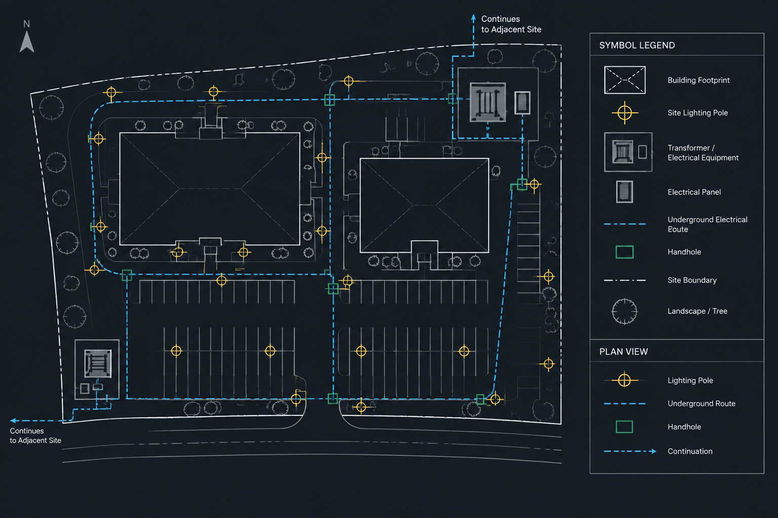
An electrical site plan shows how power, lighting, communications, and related infrastructure extend beyond a building footprint. Unlike an interior power plan, it must communicate across large outdoor areas while remaining coordinated with civil grading, utilities, landscaping, structural work, and architectural site features.
A useful electrical site plan is more than a collection of equipment symbols connected by lines. It establishes where systems begin and end, how routes relate to physical site conditions, and where another drawing or discipline provides the governing detail. The following workflow focuses on CAD drafting and documentation rather than electrical installation or field procedures.
Define the purpose of the site plan
Before drafting, identify what the sheet is expected to communicate. A project may use one combined site electrical plan or separate drawings for power distribution, site lighting, communications, security, and other systems. Separating dense information can improve readability, but only if the relationships between sheets remain clear.
Common site-plan content may include:
- Utility service points and interfaces
- Outdoor transformers, switchgear, generators, cabinets, or similar equipment
- Underground electrical and communications routes
- Handholes, pull boxes, maintenance holes, and splice locations
- Site lighting poles, bollards, and control references
- Power connections for gates, signs, pumps, shelters, or other site equipment
- Grounding or bonding features that must be coordinated graphically
- Building entry points and continuation references
- Limits of new, existing, relocated, and removed work
Not every site plan needs every category. Show information that supports design coordination and construction documentation, and direct readers to other sheets when those sheets carry the detailed requirements.
Start with a controlled site background
The electrical drawing should normally reference a coordinated site background rather than reproduce site geometry manually. Depending on the project, that background may come from civil, architectural, landscape, or survey documentation.
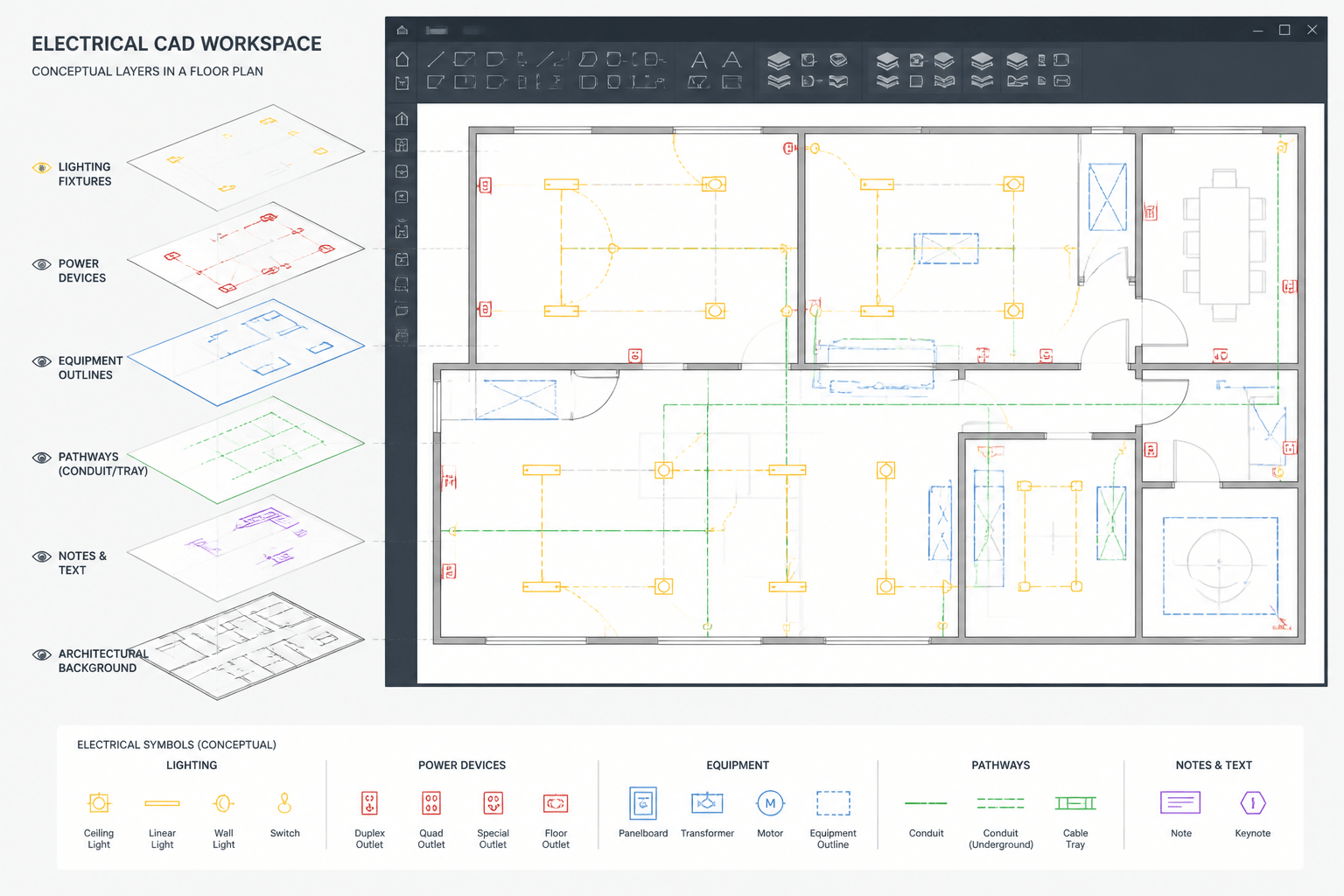
Review the background for property boundaries, building footprints, roads, curbs, sidewalks, parking areas, walls, planted zones, drainage features, and known utilities. These elements help the reader understand the electrical work, but they should appear with less graphic emphasis than the proposed electrical systems.
Confirm location and orientation
Before placing electrical information, confirm that the referenced files use a compatible origin, rotation, and unit convention. A site background that appears correct after being moved or rotated manually can become unreliable when it is updated. Record any agreed reference point or coordinate workflow in the project CAD standards so other team members can reproduce the setup.
Manage background visibility
Use layer controls, reference display settings, or approved cleanup files to suppress irrelevant detail. Dense hatch patterns, planting symbols, topographic labels, and duplicated utility notes can obscure electrical routes. Do not permanently alter another discipline’s source file merely to improve the electrical plot.
Build a clear graphic hierarchy
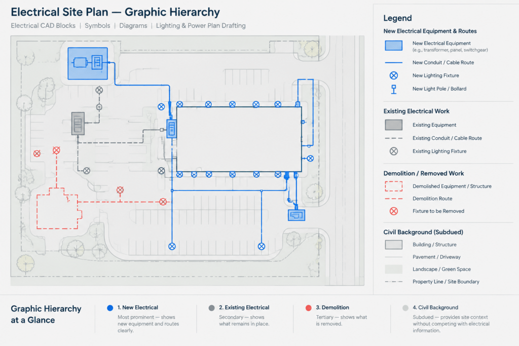
Large site drawings often contain long route lines and many overlapping systems. A consistent graphic hierarchy helps readers distinguish proposed electrical work from contextual information.
| Drawing element | Recommended graphic role | Coordination concern |
|---|---|---|
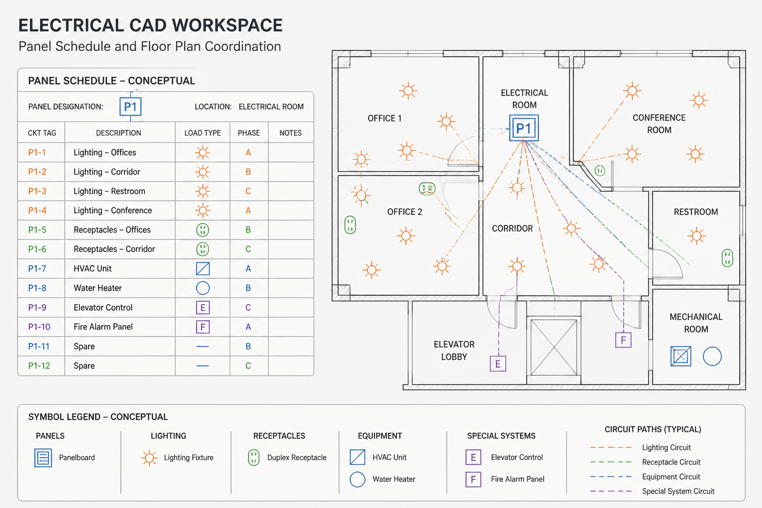
| New electrical equipment | Prominent symbol, tag, and annotation | Access, foundations, clearances, and connection points |
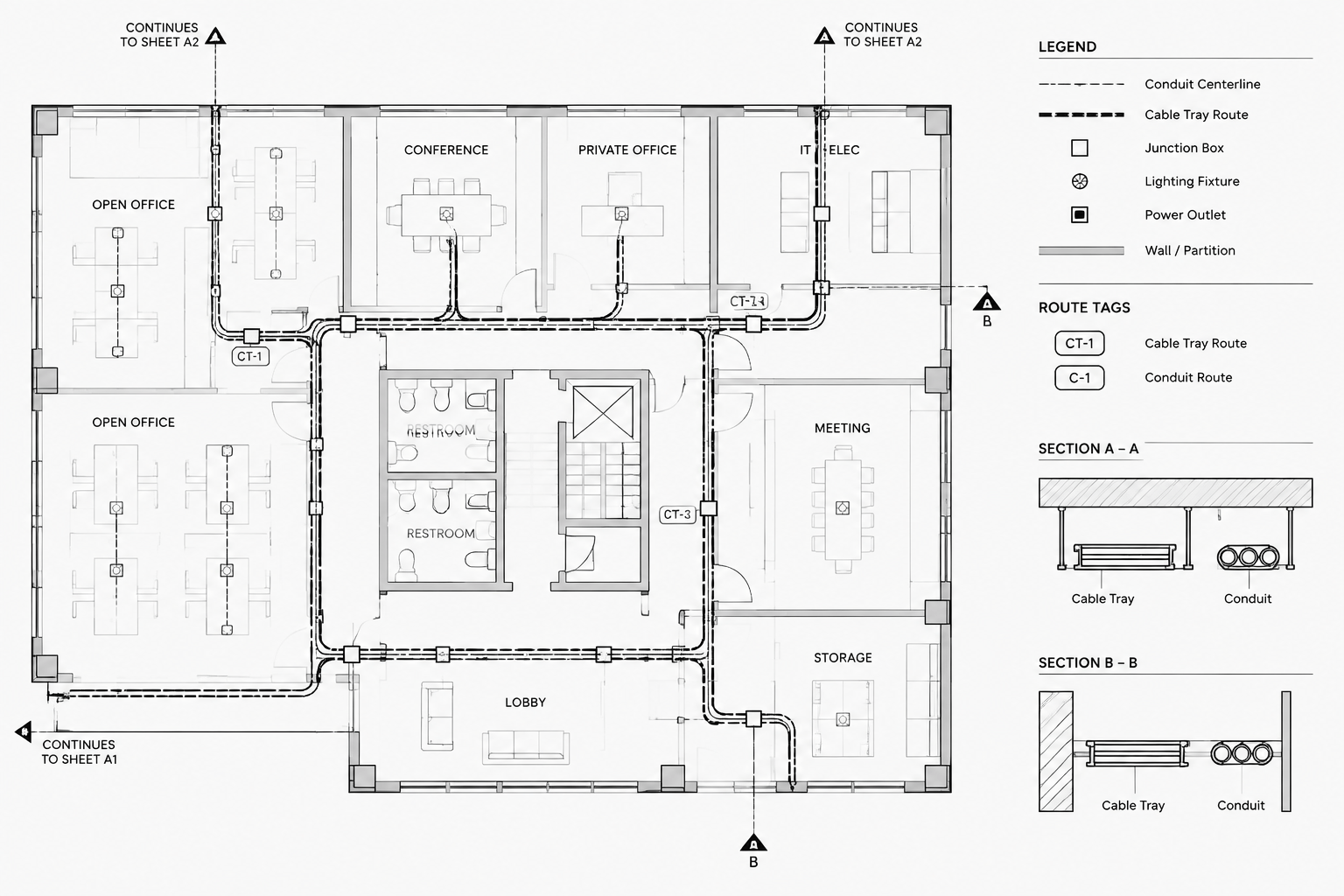
| New underground route | Distinct linetype or line pattern with route labels | Crossings, grading, structures, and other utilities |
| Existing electrical feature | Visibly different from new work | Field verification and record reliability |
| Work by others | Subdued but identifiable | Scope boundary and responsibility |
| Site background | Light contextual linework | Current reference file and issue date |
| Removal or relocation | Project-specific demolition convention | Temporary conditions and final disposition |
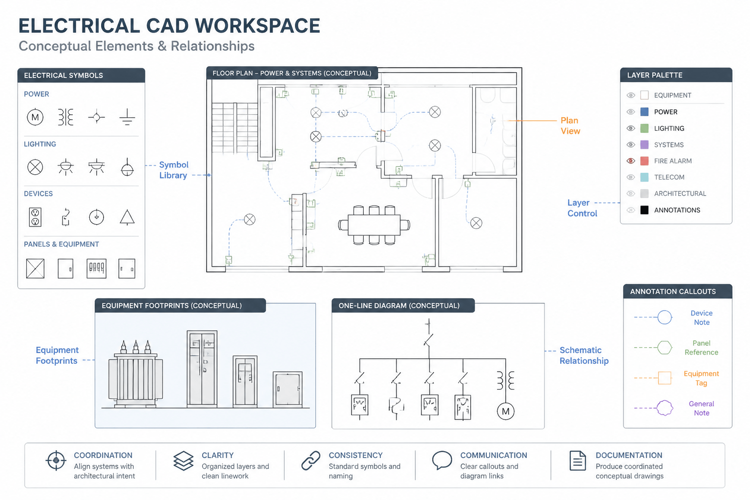
Color can assist drafting, but the plan should remain understandable in the intended plotted output. Use linetypes, lineweights, symbols, labels, and notes so that meaning does not depend entirely on screen color.
Draft routes as documented systems, not decorative lines
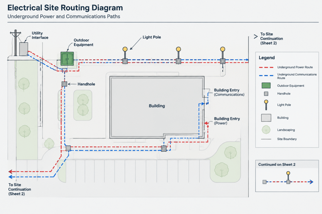
An underground route line should tell the reader what it represents and where its documentation continues. Avoid drawing an unexplained line from one symbol to another.
Route annotations can identify the system category, endpoint relationship, and relevant detail, schedule, or diagram reference. Conduit quantities, sizes, conductor information, burial requirements, and construction details should only be added when they are established by the project design. If that information belongs in a feeder schedule or detail, reference it rather than creating conflicting duplicate notes.
Keep routing geometry legible
Use deliberate path geometry that can be coordinated against physical site features. Excessive bends, tiny offsets, and line segments placed only to avoid text make the route difficult to follow. Where several systems share a general corridor, decide whether the plan should show individual routes, a grouped route with identifiers, or a reference to an enlarged plan.
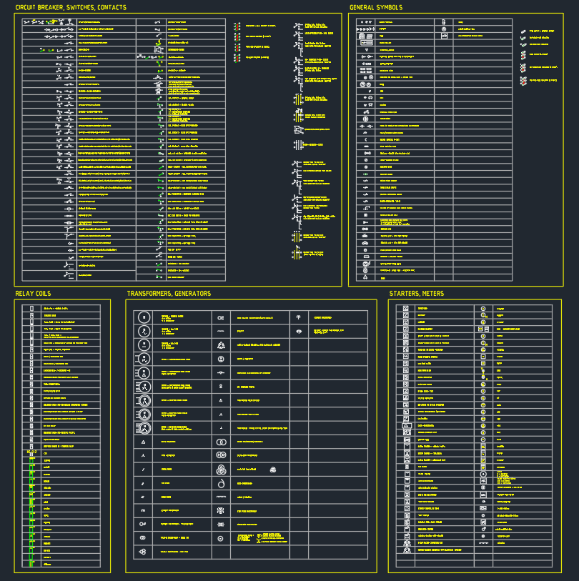
Crossings should remain visually traceable. Line breaks, jump conventions, or separate system plans may help, but the selected convention must be defined in the project legend.
Document route transitions
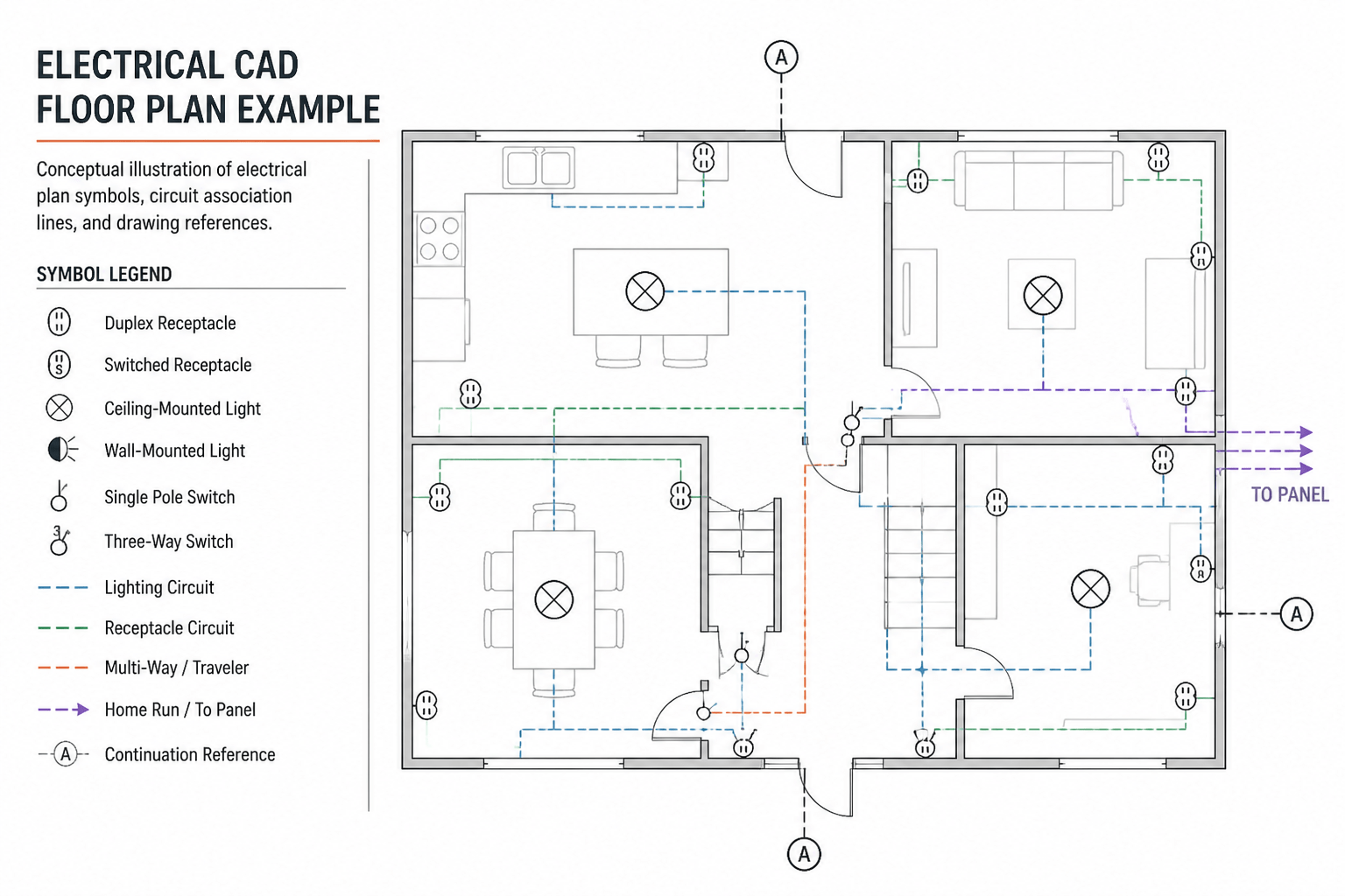
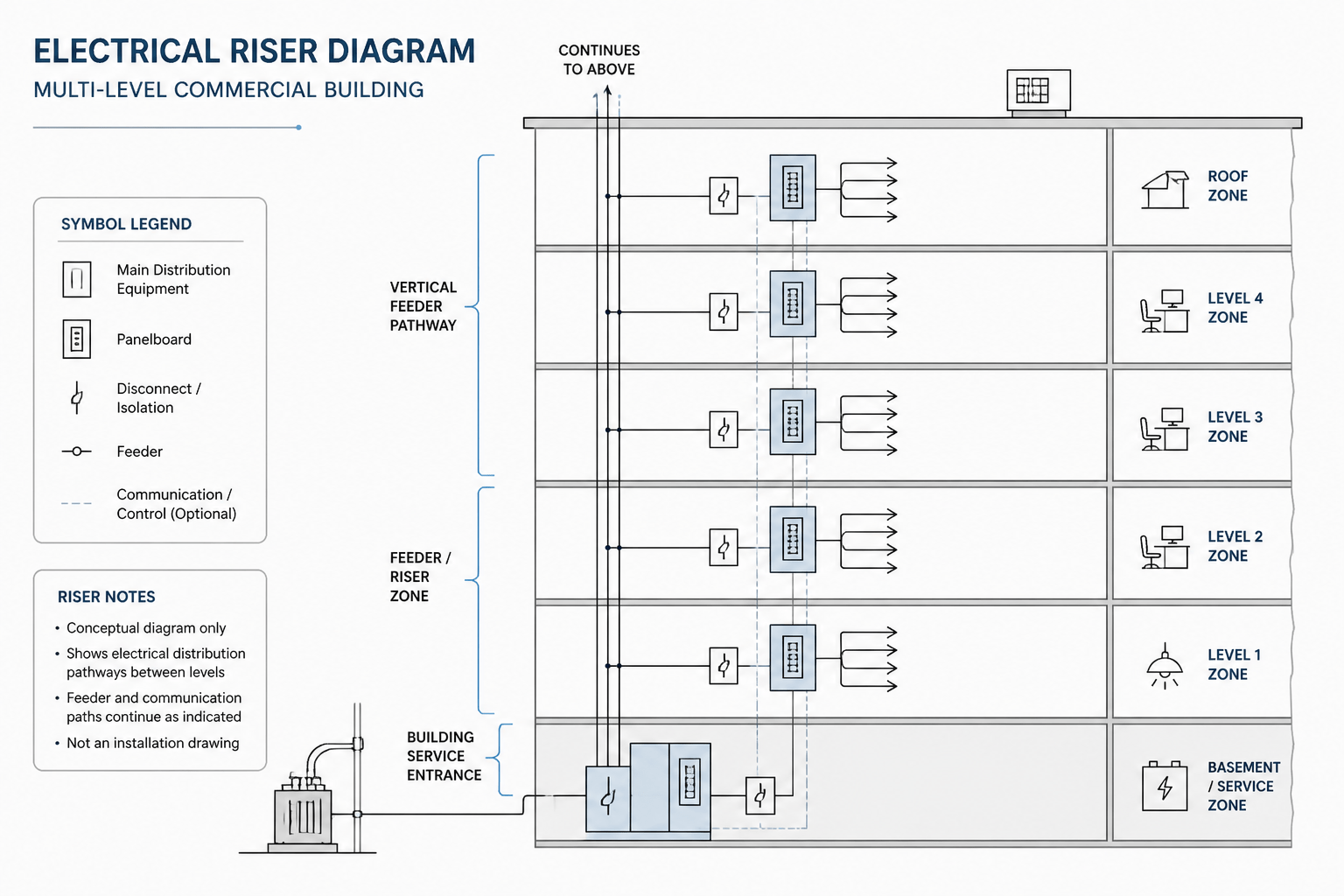
Identify transitions at building walls, equipment pads, poles, pull points, and changes between underground and exposed routing. When a route continues onto a building plan, riser diagram, or single-line diagram, use a clear continuation reference and consistent destination terminology.
Place equipment symbols with coordination in mind
CAD blocks for transformers, cabinets, poles, handholes, and other site equipment should be treated as documentation symbols unless their geometry has been verified for the selected product and project. A generic block may communicate equipment type without representing an actual enclosure, foundation, door swing, or working space.
Where physical coordination matters, distinguish between:
- The symbolic equipment marker used for identification
- The verified equipment footprint
- A foundation, housekeeping pad, or structural support outline
- Access zones or operational clearances
- Protective posts, walls, fences, or gates
These elements may come from different disciplines and should not be merged into one unexplained block. Use equipment tags that coordinate with schedules, single-line diagrams, control diagrams, and specifications. The same item should not acquire unrelated names on different sheets.
Coordinate site lighting without overcrowding the plan
A site lighting plan may show pole locations, luminaire types, circuit relationships, controls, and routing. Photometric information, fixture schedules, structural bases, and control sequences may be documented elsewhere.
When lighting shares a sheet with site power, preserve a readable distinction between lighting branch routes and larger distribution routes. Pole tags should match the luminaire schedule, while circuit or control references should align with the relevant panel and control documentation. If pole positions originate in a photometric or landscape layout, establish which drawing governs location and how changes are communicated.
Use details and enlargements strategically
A site plan should provide geographic context, not carry every installation detail. Dense utility entrances, grouped equipment, gate systems, or congested crossings may need enlargements. Use a boundary and callout that clearly identify the enlarged area and destination sheet.
Typical supporting documents may include:
- Equipment layout enlargements
- Duct bank or trench section details
- Building entry details
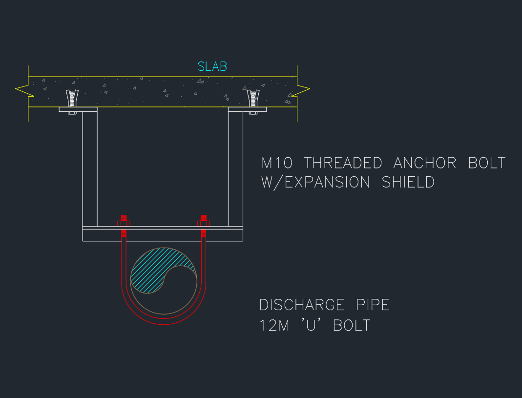
- Pole base or equipment support references
- Utility interface diagrams
- Feeder, conduit, or cable schedules
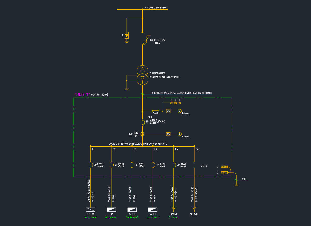
- Single-line and riser diagrams
Do not repeat detailed information on multiple drawings unless the project has a defined method for keeping it synchronized.
Perform a multidisciplinary coordination review
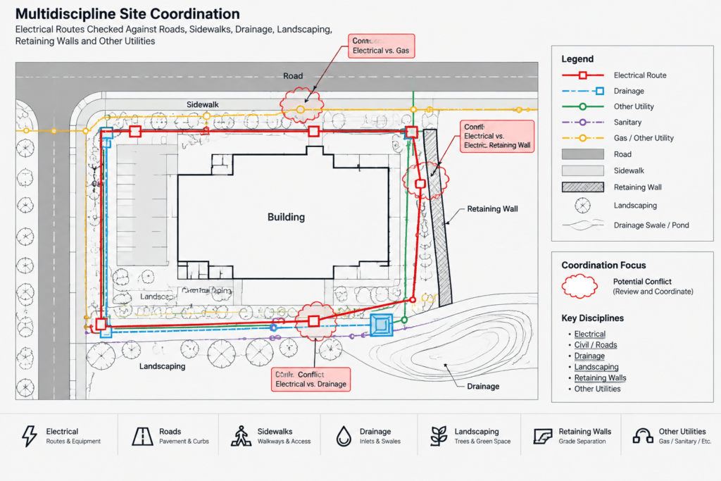
Site electrical work frequently conflicts with objects that are subtle or absent from the architectural floor plan. Compare the electrical plan with current civil, landscape, structural, utility, and specialty-system information.
A drawing-focused review should check:
- Equipment and handholes against roads, curbs, sidewalks, ramps, and accessible routes
- Routes against foundations, retaining walls, drainage systems, and known utilities
- Light poles against trees, canopies, signs, parking geometry, and security devices
- Building entry points against interior electrical rooms and plan routing
- Site equipment tags against schedules and diagrams
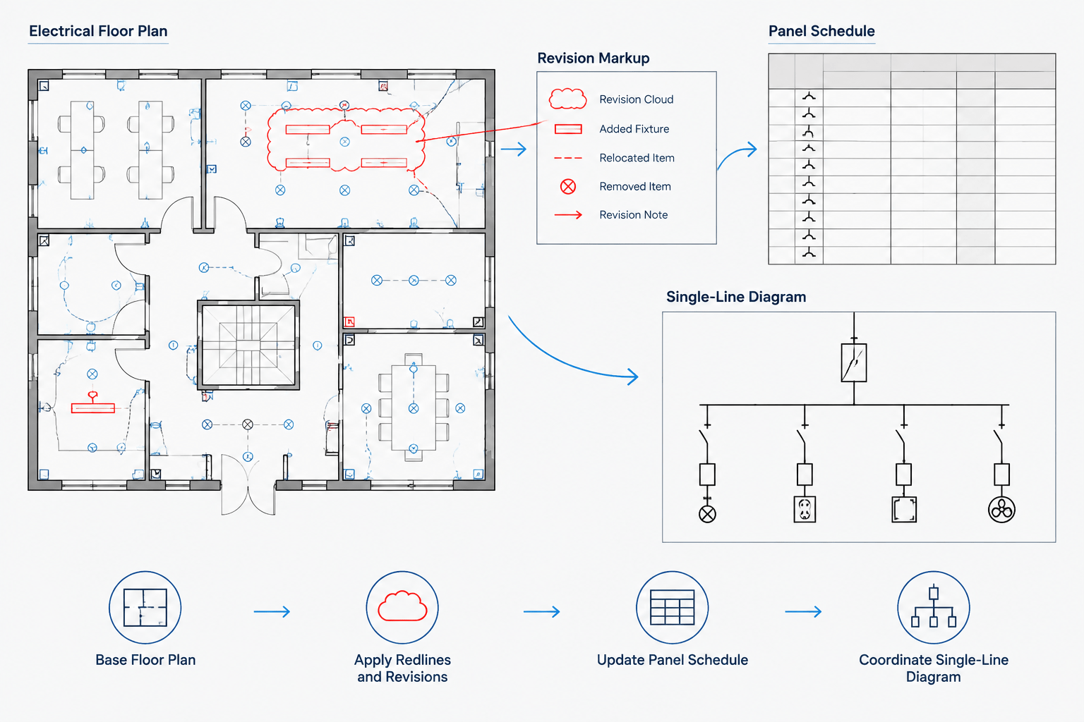
- New and existing work classifications against demolition documentation
- Plan references against actual sheet titles and detail locations
- Utility notes against current utility-provider coordination information
Where source information is uncertain, use an appropriate verification note or coordination marker rather than presenting an assumed location as confirmed.
Prepare the sheet for issue
Plot the drawing using the intended sheet size and output settings. Inspect long routes for broken linetype display, clipped labels, hidden crossings, and annotation that becomes unreadable at print scale. Confirm that the legend includes every project-specific symbol or line convention used on the plan.
Finally, review the site plan together with the single-line diagram, panel or feeder schedules, lighting schedules, enlarged plans, and details. The plan should answer where an item is located and how it connects geographically, while the supporting documents explain system relationships and project-specific requirements. That division of information produces a cleaner CAD file and a more dependable electrical drawing set.
Leave a Reply
You must be logged in to post a comment.