
Choosing between an electrical schematic, wiring diagram, and connection diagram starts with the question the drawing must answer. Although these documents can represent the same equipment, each presents a different view of the electrical system and supports a different stage of drafting, coordination, or review.
This guide compares their purposes, information boundaries, and CAD organization. It also explains how shared device, cable, connector, and terminal identifiers help keep related drawings coordinated when terminology varies between project teams.
Electrical wiring diagrams, schematics, and connection diagrams may describe the same system, but they do not communicate the same information. A schematic explains functional relationships. A wiring diagram shows how equipment is wired. A connection diagram concentrates on specific point-to-point terminations between devices, panels, cables, or terminal blocks.
The terminology is not completely uniform across industries, manufacturers, and project teams. One organization may call a drawing a wiring diagram while another calls a similar document an interconnection diagram. The practical solution is not to rely on the title alone. Define each drawing type in the project drawing list or legend, and make its intended level of detail clear.
Three drawings, three documentation purposes
The best drawing type depends on the question a reader needs to answer. If the question is about operating logic, use a schematic. If it is about terminals and conductors inside an assembly, use a wiring diagram. If it is about connections between assemblies or field devices, use a connection diagram.
| Drawing type | Primary purpose | Typical information | Usually deemphasized |
|---|---|---|---|
| Schematic | Explain electrical function and logic | Contacts, coils, protective devices, control relationships, signal flow, and logical connections | Physical placement, cable routing, and exact conductor arrangement |
| Wiring diagram | Document how components or terminals are wired | Device tags, terminal designations, conductor references, jumpers, plugs, and internal connections | Building-scale routing and detailed operating sequences |
| Connection diagram | Show point-to-point interfaces between equipment | From-to connections, cable IDs, terminal points, connector pins, and destination equipment | Internal device logic and unrelated assembly wiring |
These categories can overlap. For example, a panel wiring diagram may include outgoing field connections, while a connection diagram may show a limited amount of internal terminal information. What matters is that the drawing boundary is intentional and understandable.
What a schematic should communicate
A schematic represents electrical behavior rather than physical arrangement. Symbols are organized to make the circuit easier to follow. Components that are physically far apart may appear next to each other, while contacts belonging to one device may be distributed across several parts of the drawing.
A useful schematic commonly communicates:
- Functional relationships between sources, switching devices, loads, and controls
- The normal state or intended representation of contacts and switching elements
- Device identifiers that connect related coils, contacts, and equipment
- Signal or control paths presented in a consistent reading direction
- Cross-references to related drawing areas when a device is shown in more than one location
A schematic should not be mistaken for an installation map. A line between two symbols establishes an electrical relationship, but it may not identify a cable route, raceway path, field junction, or physical terminal unless those details are deliberately added.

CAD layout for schematics
Build the sheet around logical reading order. Keep conductors aligned, minimize unnecessary line crossings, and use consistent spacing between functional groups. Repeated symbols should come from a controlled block library so that contacts, coils, switches, and other devices use a common graphic language.
When related components are separated, cross-references should point to stable sheet or drawing locations. Avoid manually typed references that can become outdated when a rung, sheet, or circuit group moves.
What a wiring diagram should communicate
A wiring diagram moves closer to the physical assembly. It can show how components in a control panel, equipment enclosure, packaged unit, or other assembly connect to terminals and to one another. Unlike a schematic, its structure may reflect terminal strips, connectors, component groupings, or enclosure subdivisions.
Depending on project scope, a wiring diagram may include:
- Equipment and component tags
- Terminal designations and connector pin references
- Conductor or wire identifiers
- Internal jumpers and factory connections
- Field connection boundaries
- References to cable schedules or external connection drawings
Do not force every physical characteristic into one sheet. Showing exact conductor routing, enclosure geometry, device placement, and operating logic together can make the drawing difficult to maintain. A panel layout can document physical component locations, while the wiring diagram documents electrical connections.
Separating internal and field wiring
One of the most useful graphic distinctions is the boundary between internal assembly wiring and field-installed connections. That boundary may be communicated with line conventions, labeled regions, terminal strips, connector interfaces, or clear notes. The chosen method should be explained in the legend rather than assumed.
Also distinguish documented connections from spare terminals, reserved points, and unused connector positions. Empty graphic space is not a reliable substitute for an explicit status.
What a connection diagram should communicate
A connection diagram focuses on interfaces. It answers questions such as: Which cable connects two pieces of equipment? Which conductor lands on which terminal? Where does a signal leave one assembly and enter another?
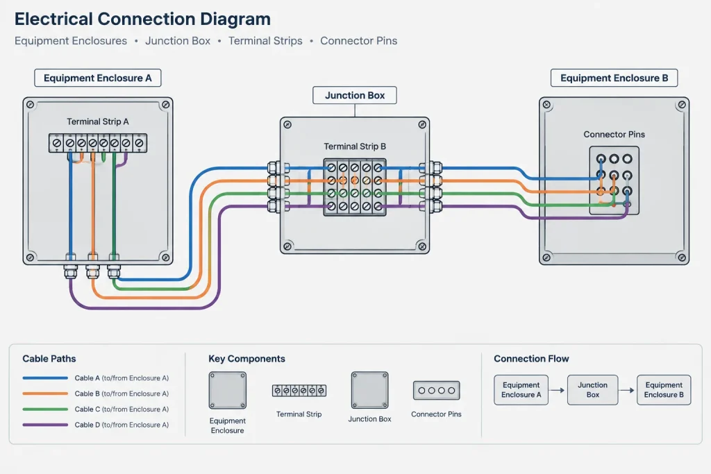
This drawing type is especially useful where the system contains multiple panels, packaged assemblies, field devices, junction boxes, terminal blocks, or detachable connectors. The diagram can isolate the project-specific connections without reproducing all internal wiring.
A connection diagram may be organized as:
- A graphical point-to-point diagram with equipment blocks and connecting lines
- A terminal-to-terminal drawing arranged around strips or connectors
- A tabular from-to list coordinated with a graphical overview
- A cable-centered diagram showing cores or conductors between endpoints
Choose one primary organizing principle. If the sheet is organized by cable, keep cable identities prominent. If it is organized by equipment, make origins and destinations easy to scan. Mixing cable-based, terminal-based, and functional organization without a hierarchy often creates duplicate or conflicting information.
Coordinate the drawings through shared identifiers
A drawing set becomes reliable when each view uses the same identity for the same object. The symbol can change between a plan, schematic, wiring diagram, and connection diagram, but its device tag should remain coordinated.
Useful shared identifiers include:
- Equipment and device tags
- Panel, enclosure, and assembly names
- Terminal strip and terminal designations
- Cable and conductor IDs
- Connector and pin references
- Drawing and detail cross-references
Use CAD attributes or controlled data fields where practical, but do not assume automation guarantees accuracy. Attribute values still require review for duplicates, missing entries, obsolete references, and inconsistent formatting.
A practical CAD documentation workflow
1. Define the information boundary
Before drafting, state what the sheet is responsible for showing. For example, a schematic may define control logic, while a connection diagram defines external terminations. This prevents two drawings from independently documenting the same connection in different ways.

2. Establish the source of each identifier
Decide where device tags, cable IDs, and terminal names originate. The authoritative source might be a controlled equipment list, terminal schedule, cable schedule, or project database. Avoid creating new identifiers independently on each sheet.
3. Build symbols around drawing purpose
Do not use a plan symbol as a substitute for a schematic symbol merely because both represent the same device. Maintain related block families where each block uses the correct graphic form but retains coordinated identity fields.
4. Draft interfaces before decorative detail
Place equipment boundaries, terminal strips, connectors, and major functional groups first. Add conductor lines, labels, and cross-references after the drawing structure is stable. This reduces cleanup when the arrangement changes.
5. Run a from-to review
Trace representative connections in both directions. Confirm that each origin has a destination, each destination exists, and intermediate terminals or junctions are accounted for. Review references at sheet boundaries rather than checking only the center of each drawing.
6. Compare related documents before issue
Check the schematic against the wiring and connection documents. A device added to the schematic may require terminals, conductors, cables, and schedule entries elsewhere. A terminal revision may affect several sheets even when the functional logic has not changed.
Common drafting problems
- Using titles inconsistently: If similar sheets use different meanings for wiring and connection diagrams, readers cannot predict their content.
- Duplicating complete circuits: Repeating the same connection on several drawings creates multiple maintenance points.
- Missing drawing boundaries: Readers cannot tell whether wiring is internal, vendor-provided, or part of the project field scope.
- Uncoordinated tags: A device receives different identifiers on the schematic, layout, and cable schedule.
- Unclear line crossings: Connection points and nonconnecting crossings are not graphically distinct.
- Overloaded sheets: Functional logic, physical placement, cable routing, and terminal details compete in one view.
- Orphaned references: A cross-reference points to a deleted sheet, moved circuit, or renamed device.
Final drawing review checklist
- Does the sheet title match the information actually shown?
- Is the purpose and boundary of the drawing evident?
- Are device, cable, connector, and terminal identifiers coordinated?
- Can each important connection be traced from origin to destination?
- Are internal and external connections distinguishable?
- Are junctions and nonconnecting line crossings unambiguous?
- Do cross-references lead to current drawing locations?
- Have duplicate descriptions of the same connection been reconciled?
- Are symbols and line conventions explained in the legend?
- Have related schedules and equipment layouts been checked?
The central distinction in wiring diagrams vs. schematics is purpose. Schematics explain function, wiring diagrams document assembly connections, and connection diagrams clarify interfaces. When each drawing has a defined responsibility and all three share controlled identifiers, the documentation becomes easier to draft, review, revise, and use.
Choose the drawing for its intended reader
Drawing selection should account for who will use the document and what decision that person needs to make. A controls reviewer may need to follow operating relationships, a panel drafter may need to coordinate internal terminations, and a field-documentation reviewer may need to trace cables between equipment. Giving every audience the same overloaded drawing usually reduces clarity.
Before selecting a format, ask:
- Is the reader following function? Emphasize schematic relationships and logical signal paths.
- Is the reader verifying assembly wiring? Emphasize components, terminals, conductors, connectors, and jumpers.
- Is the reader tracing an interface? Emphasize origins, destinations, cables, terminal points, and equipment boundaries.
- Is physical location the main concern? Coordinate with an equipment layout, plan, or enclosure drawing rather than forcing location data into the electrical diagram.
Treat the drawing title as a classification, not a complete specification
A title such as wiring diagram does not by itself define the expected content. The drawing list, legend, drafting standard, or project documentation plan should state whether the sheet covers internal wiring, external wiring, terminal details, cable interfaces, or a combination of these subjects.
When receiving drawings from another organization, review the information shown before assigning a category. Renaming a document does not change its information boundary, and similar titles do not guarantee that two drawings serve the same purpose.
Manage revisions across the drawing set
A connection change can affect more than the sheet where it was first identified. Device tags, terminal assignments, conductor references, cable records, connector pins, schedules, and cross-references may all require coordinated review. Revision checks should therefore follow the affected connection across document boundaries rather than stopping at the edited sheet.
A useful quality-control approach is to select a changed device or cable and trace its identity through every relevant drawing and schedule. This reveals stale references, duplicate identifiers, and differences between functional intent and documented terminations.
Frequently asked questions
Is a schematic the same as a wiring diagram?
No. A schematic primarily explains electrical function and logical relationships. A wiring diagram focuses more closely on how components, conductors, connectors, or terminals are connected within an assembly.
What is the difference between a wiring diagram and a connection diagram?
A wiring diagram commonly documents connections within equipment or an enclosure. A connection diagram emphasizes interfaces between equipment, panels, terminal blocks, junction points, cables, or field devices. Project terminology can vary, so the stated drawing boundary remains important.
Can one drawing combine schematic and connection information?
Yes, but the combined content must remain readable and clearly defined. If logical operation, internal wiring, and external interfaces compete for attention, separating them into coordinated drawings generally produces a more maintainable document set.
Should electrical symbols look identical on every drawing type?
Not necessarily. A device may use different graphic forms on a plan, schematic, wiring diagram, or connection diagram. Its identifying tag and related data should remain coordinated even when the symbol changes.
How should a drafter handle inconsistent drawing terminology?
Review the actual content, identify the intended audience, and define the document in the drawing list or legend. Do not rely on the file name or sheet title alone to determine what information should be present.
What should be checked after a terminal assignment changes?
Review the affected wiring and connection diagrams along with related cable records, connector references, schedules, equipment tags, and cross-references. The functional schematic may also require review if the change alters the documented circuit relationship.


Leave a Reply
You must be logged in to post a comment.