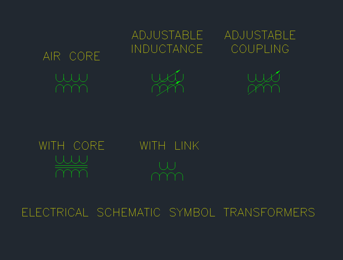
Schematic transformer symbols provide a compact way to show transformer relationships in electrical drawings without depicting the physical construction of the equipment. In a CAD workflow, a well-organized symbol collection can help designers communicate winding relationships, circuit connections, and the role of a transformer within a larger system.
This resource focuses on schematic transformer symbols for AutoCAD and other CAD applications. Use the collection as a drafting reference alongside project-specific symbols, drawing conventions, legends, and engineering review procedures. A symbol library can support consistent documentation, but the selected symbol should always match the intent and level of detail required by the drawing.
Discover a comprehensive DWG file featuring detailed schematic transformers symbols, perfect for electrical and electronic CAD projects. This CAD block collection includes various transformer symbols commonly used in circuit diagrams, making it an essential resource for engineers, architects, and designers. The file is fully compatible with AutoCAD and other popular CAD software, ensuring seamless integration into your design workflow. Use these schematic transformers symbols to accurately represent transformers in your electrical layouts, enhance your project documentation, and streamline the drafting process. Ideal for both educational and professional applications, this DWG file simplifies your transformer symbol needs.
Please log in or register to download this file.
What schematic transformer symbols communicate
Transformer symbols typically represent magnetically related windings and the electrical relationship between circuit portions. Depending on the drawing convention, the symbol may distinguish the winding sides, show a core relationship, or identify connection details such as taps or polarity. The exact graphic should be read together with the drawing legend and nearby labels.
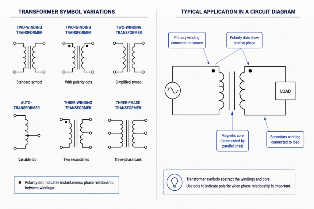
In a schematic, the symbol is primarily functional rather than physical. It explains how a transformer participates in a circuit or distribution concept, while equipment layouts and installation drawings may require additional information about enclosure arrangement, terminals, clearances, or connections. These drawing types should not be treated as interchangeable.
Using transformer symbols in electrical CAD drawings
- Choose the drawing context: A power schematic, single-line diagram, control diagram, and equipment layout may use different levels of graphic detail.
- Check the legend: Confirm how the project identifies transformers, winding sides, terminals, grounding relationships, and related notes.
- Maintain readable connections: Position the symbol so conductors, terminals, and annotations remain clear at the intended drawing scale.
- Use consistent CAD organization: Place symbols, connection graphics, text, and reference annotations on appropriate layers according to the project drafting standard.
- Review surrounding devices: Read the transformer together with protective devices, switches, panels, loads, and other connected equipment shown in the drawing.
Reference guide for related drawing topics
- Electrical symbols and legends: Explain the graphic language used throughout a drawing set.
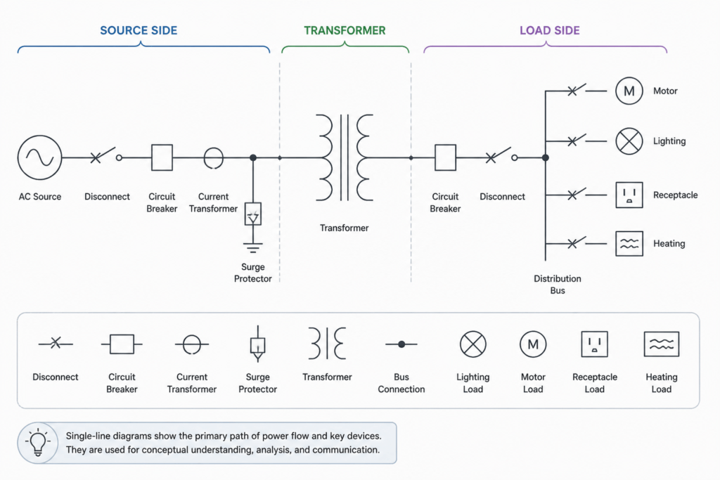
- Single-line diagrams: Show simplified relationships between sources, transformers, distribution equipment, and loads.
- Lighting and power plans: Place electrical equipment and circuits in relation to the architectural plan.
- Panel schedules: Organize circuit and load information that may correspond to equipment shown elsewhere.
- CAD blocks and layers: Support repeatable drafting, visibility control, and consistent documentation.
- Cable and conduit drawings: Provide a more physical view of routing and connection relationships than a schematic alone.
Drafting checks before publication
Before issuing a drawing, check that the transformer symbol is legible, its connections terminate clearly, its labels agree with the project terminology, and its appearance is consistent with the rest of the drawing set. Also verify that the CAD block does not carry unwanted layers, attributes, linework, or annotation that could confuse later editing.
This DWG resource is best treated as a drafting aid and reference collection. It does not replace project calculations, equipment selection, design review, or applicable engineering requirements.
Frequently asked questions
What is a schematic transformer symbol?
It is a simplified graphic used to represent a transformer and its electrical relationships in a schematic, single-line diagram, or related drawing.
Can these symbols be used in AutoCAD drawings?
The source describes the DWG collection as compatible with AutoCAD and other popular CAD software. Users should still check the file behavior, units, layers, attributes, and project drafting conventions before incorporating it into a drawing set.
Are schematic symbols the same as equipment layout symbols?
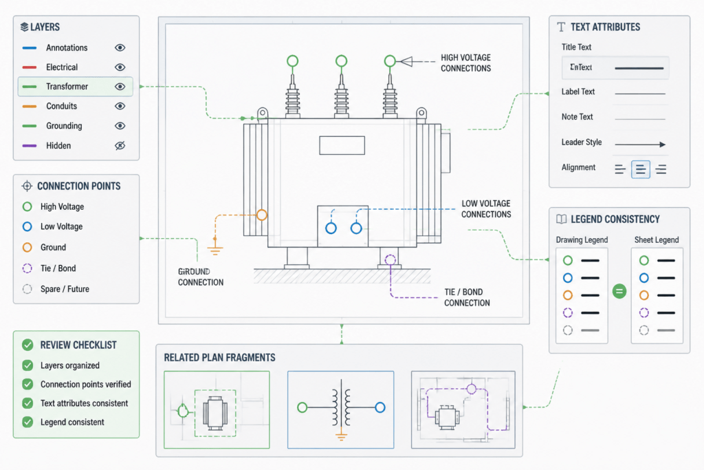
No. Schematic symbols describe electrical function and relationships, while equipment layout graphics are generally used to communicate physical placement, arrangement, or connection context.
Why does the drawing legend matter?
The legend defines how symbols and abbreviations are interpreted within a particular project. It helps prevent a familiar graphic from being read differently than the designer intended.
What should be checked after inserting a transformer block?
Review its orientation, connection points, layer behavior, text and attributes, visual clarity, and consistency with nearby symbols. Confirm that the block supports the intended drawing purpose without implying information that has not been engineered or documented.



Leave a Reply
You must be logged in to post a comment.