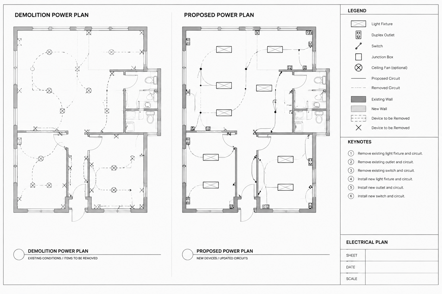
Electrical renovation documents must make the transition from existing conditions to completed work easy to follow. That requires more than placing demolition marks over an old floor plan. The drafter must establish a consistent graphic language for retained, removed, relocated, proposed, and unverified items.
This guide explains how to organize electrical demolition and renovation plans in CAD while preserving the distinction between documented design intent and conditions that require field verification. It focuses on drawing structure, symbols, layers, annotations, coordination, and quality control rather than construction procedures.
An electrical renovation drawing must explain more than where new devices will be installed. It also needs to identify what remains, what is removed, what is relocated, and how existing systems relate to the proposed work. If those conditions are not clearly separated, contractors, reviewers, estimators, and facility personnel may interpret the same plan differently.
A well-organized electrical demolition plan establishes the starting condition for the renovation set. The corresponding new-work plan then communicates the intended result. Together, these drawings create a traceable documentation sequence without attempting to prescribe field procedures. Existing conditions must still be verified through surveys, record documents, and appropriate project investigation.
What an Electrical Demolition Plan Communicates
An electrical demolition plan is a drawing showing existing electrical items affected by a project. Depending on the scope, it may identify lighting fixtures, receptacles, switches, equipment connections, panels, feeders, raceways, communications outlets, fire alarm devices, or other systems.
The plan usually classifies visible items by an action such as:
- Existing to remain
- Existing to be removed
- Existing to be relocated
- Existing to be disconnected or made inactive
- Existing to be protected during construction
- Existing condition requiring field verification
These are documentation categories, not field-work instructions. The project team must determine the actual disconnection, removal, temporary service, and safety procedures.
Separate Existing Conditions from Proposed Work
Trying to show demolition and new construction with the same graphic treatment is a common source of confusion. A reader should be able to tell immediately whether a symbol represents an existing device, a removed device, or a proposed installation.
For a modest renovation, demolition and new work may appear on separate plans covering the same area. On a complex project, separate sheets are usually clearer because they reduce overlapping symbols and annotations. When both conditions must be shown together, use a deliberate hierarchy of layers, linetypes, screening, and notes.
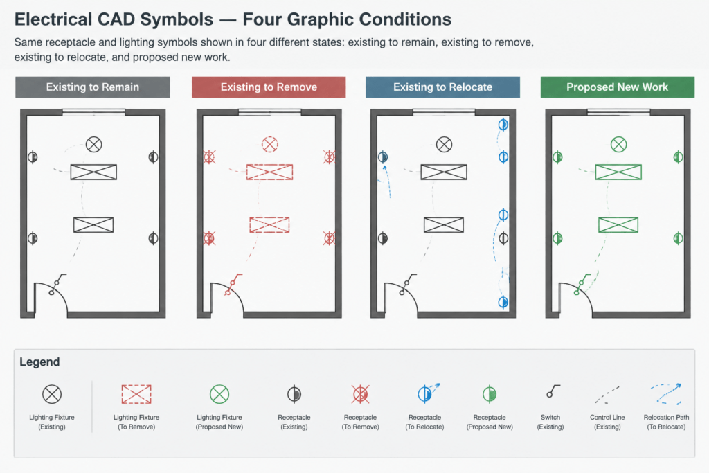
| Drawing condition | Typical graphic approach | Documentation purpose |
|---|---|---|
| Existing to remain | Screened or visually subdued linework | Provides context without competing with the scope |
| Existing to remove | Distinct demolition linetype, symbol treatment, or keyed note | Identifies items affected by demolition |
| Existing to relocate | Demolition identification plus a relocation tag | Connects the original condition to the proposed location |
| New work | Prominent continuous linework and standard new-work symbols | Shows the completed design intent |
| Unverified condition | Specific note or verification marker | Flags information that should not be treated as confirmed |
The exact graphic convention should follow the project CAD standard and sheet legend. Do not rely on color alone because drawings may be viewed or printed in monochrome.
Build a Reliable Existing-Conditions Base
Renovation drawings often begin with architectural backgrounds, prior electrical files, scanned record drawings, survey notes, photographs, or a combination of sources. These references do not automatically represent current field conditions.
Before drafting scope, document the source and status of the available information. Keep confirmed survey information distinguishable from copied record information when uncertainty could affect interpretation. Avoid adding precise-looking circuit, routing, or equipment data merely because the CAD file has space for it.
Check the background before adding symbols
- Confirm that the architectural plan represents the renovation area.
- Compare room names, partitions, doors, ceilings, and fixed equipment with the latest coordination background.
- Identify areas where walls or ceilings will be removed.
- Note whether the electrical survey covered concealed conditions or only visible devices.
- Determine which existing panel and circuit references have been verified.
A CAD plan should communicate uncertainty honestly. A general note cannot always replace a targeted verification note located beside the affected item.
Create Condition-Based CAD Layers
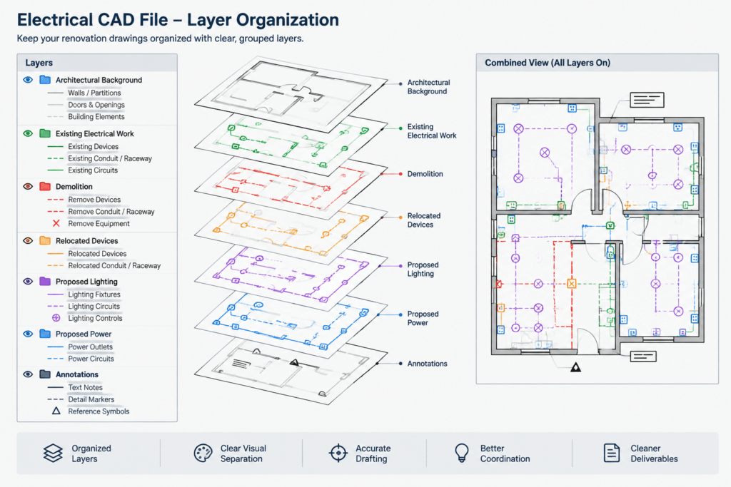
Condition-based layers make demolition drawings easier to edit, review, and plot. They also help prevent an existing symbol from being mistaken for a proposed device after backgrounds are updated.
A layer system may separate content by electrical discipline, drawing condition, and object type. For example, lighting demolition should not be mixed indiscriminately with proposed power devices or architectural background geometry. The precise layer names are less important than consistent logic across the set.
Useful layer groupings include:
- Existing electrical items to remain
- Electrical demolition symbols and circuit lines
- Proposed lighting and controls
- Proposed power devices and equipment connections
- Relocation tags and cross-references
- Demolition notes and keynotes
- Unverified or survey-dependent information
- Architectural and consultant backgrounds
Layer controls should support plotting as well as drafting. Test the printed or exported sheet to confirm that screened existing work remains legible and that demolition markings are distinguishable without overwhelming the plan.
Use Symbols and Notes as a Combined System
A demolition symbol by itself may not explain the full scope. For example, crossing out a receptacle symbol suggests removal, but it does not clarify whether associated raceway is concealed, shared, abandoned, reused, or outside the documented scope.
Use symbols for quick recognition and notes for project-specific intent. A concise keynote can address an unusual condition without filling the plan with repetitive text. However, generic notes should not be used to conceal unresolved design questions.
Keep the legend condition-specific
The electrical legend should show how existing, demolished, relocated, and new symbols differ. If the same base symbol is used for several conditions, demonstrate each variation. Include abbreviations that actually appear on the sheets rather than filling the legend with unrelated library content.
Symbols imported from a CAD block library should be reviewed before use. Check their insertion point, layer behavior, text attributes, plot appearance, scale, and compatibility with the project legend. A familiar-looking block does not prove that its meaning matches the current drawing standard.
Document Relocated Devices Clearly
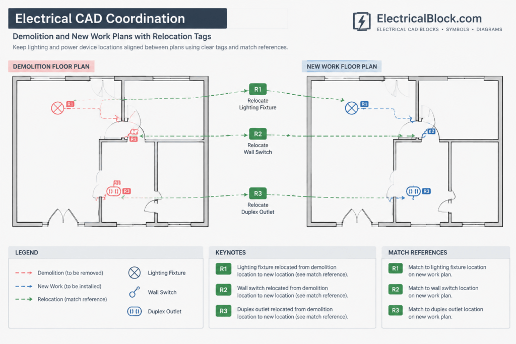
Relocation is best treated as a relationship between two drawings. The demolition plan identifies the original device and indicates that it is to be relocated. The new-work plan shows its intended destination and identifies it as relocated equipment rather than an unrelated new item.
Use a shared tag, keynote, or equipment identifier to connect the two locations. This is particularly important when several similar fixtures or devices are being reused. Avoid drawing ambiguous dashed lines across unrelated rooms unless the project convention clearly defines them.
If reuse depends on condition, compatibility, or owner acceptance, state that dependency rather than presenting reuse as confirmed. The drawing should not imply that existing equipment is suitable for a new application without verification.
Coordinate Demolition with New Work
Every significant demolition action should be checked against the proposed design. Removing a wall-mounted device may affect downstream devices, control relationships, circuit continuity, equipment interfaces, or architectural finishes. The CAD review should therefore compare demolition and new-work plans side by side.
Useful coordination checks include:
- Do removed lighting fixtures correspond with the revised reflected ceiling plan?
- Are relocated switches shown at both their original and proposed locations?
- Are equipment identifiers consistent between electrical and mechanical drawings?
- Do panel references agree across plans, schedules, and diagrams?
- Are devices shown to remain located on walls or ceilings that also remain?
- Are abandoned annotations, circuit lines, and tags removed from the new-work plan?
- Do drawing extents and match lines cover the same renovation area?
Where selective demolition affects a single-line or riser diagram, update the diagram rather than relying only on a floor-plan note. The plan shows location; the diagram explains the documented system relationship.
Handle Circuit Information Carefully
Existing circuit information is frequently incomplete. Record drawings may be outdated, labels may have changed, and visible devices may not reveal concealed circuit routing. Do not convert assumptions into authoritative CAD labels.
When circuit information has been verified, carry it consistently between the plan and panel documentation. When it has not been verified, use an appropriate project note or placeholder that clearly indicates its status. Avoid tracing speculative circuit lines simply to make the plan appear complete.
Renovation documentation should also distinguish between removing a device symbol and changing the documented circuit relationship. Those actions are related, but they are not graphically interchangeable.
Plan Sheet Organization for Renovation Sets
Sheet titles and view labels should make the phase and drawing condition obvious. A reader should not need to inspect individual symbols to determine whether a plan represents demolition or proposed construction.
A practical sequence may include an existing-conditions reference, an electrical demolition plan, a new-work lighting plan, a new-work power plan, and updated schedules or diagrams. The required sequence varies with project scope, so include only the views needed to explain the work clearly.
Use the same crop, orientation, room references, and match-line logic where possible. Consistent views make comparison easier and reduce the risk that a scope item disappears between sheets.
Final CAD Quality-Control Checklist
- Confirm that every symbol type is defined in the legend.
- Check that existing, demolished, relocated, and new work remain distinguishable in the final plot.
- Remove duplicate blocks and accidental overlapping symbols.
- Verify that keynotes point to the intended objects.
- Compare demolition and new-work views for missing or conflicting items.
- Review panel names, equipment tags, and circuit references across all related documents.
- Check background files for outdated room names or partition layouts.
- Confirm that revision clouds and markers describe the current issue rather than earlier edits.
- Purge unused library content only when doing so will not disrupt required project data.
- Flag field-dependent information instead of presenting assumptions as confirmed conditions.
A Clear Record of Change
The main purpose of an electrical demolition plan is to document change. Good renovation drawings allow a reader to understand the existing context, the affected scope, and the proposed result without decoding inconsistent graphics.
Condition-based layers, disciplined symbol use, coordinated notes, and side-by-side drawing checks make that record more reliable. CAD blocks support the process, but clarity comes from how each block is classified, annotated, and connected to the rest of the electrical document set.
Use a Change-Based Review Method
A useful final review follows each affected item through its documented change. Start with the existing condition, identify the demolition action, and then locate the corresponding result on the new-work plan. This approach helps reveal devices that were marked for relocation but never placed, proposed equipment without a documented source condition, and notes that no longer match the graphics.
Reviewers should also distinguish between an object change and a system change. Moving or removing a symbol may have consequences for circuit references, controls, schedules, diagrams, and equipment identifiers. Updating only the floor-plan graphic can leave conflicting information elsewhere in the drawing set.
Control Background and Reference File Status
External references and consultant backgrounds should be managed as controlled project inputs. Record the background identity and status through the project documentation workflow so that team members can recognize when a plan was coordinated against an earlier layout.
Avoid permanently obscuring important differences between background versions. When partitions, room names, ceilings, or equipment locations change, compare the revised reference with the electrical scope before accepting the update. A clean-looking reload does not confirm that electrical annotations still point to the correct objects.
Check Model and Sheet Presentation Separately
Correct model-space organization does not guarantee a readable sheet. Viewport settings, layer overrides, screening, lineweights, annotation visibility, and plot styles can alter the apparent meaning of renovation graphics.
Inspect both the editable CAD content and the issued output. Demolition linework must remain recognizable after plotting, while existing context should remain visible enough to orient the reader. Tags, leaders, and notes should be checked at their intended sheet presentation rather than judged only while zoomed into the model.
Preserve an Auditable Drawing Narrative
Revision management should retain a clear account of what changed and which documents were coordinated. Temporary drafting marks, obsolete alternatives, and abandoned annotations should not remain in an issued view unless the project convention intentionally uses them.
The completed set should communicate a coherent narrative: what was understood to exist, what is affected, what is intended to remain, and what the proposed documents show after renovation. Where that narrative depends on unresolved information, the uncertainty should be visible at the relevant location instead of being hidden by polished CAD graphics.
Frequently Asked Questions
Should demolition and new work be shown on the same electrical plan?
They may be combined when the scope remains readable and the project drawing convention clearly differentiates each condition. Separate plans are often easier to compare when overlapping devices, circuit lines, notes, or architectural changes would make a combined view difficult to interpret.
How should existing electrical equipment be represented in CAD?
Use the project-approved layer, symbol, linetype, screening, and annotation conventions. Existing equipment to remain should be visually distinct from equipment to remove, relocate, or replace. The final plotted sheet should preserve those distinctions without depending only on color.
What is the clearest way to document a relocated device?
Identify the device at its original location on the demolition plan and at its intended location on the new-work plan. A shared tag, identifier, or keynote should connect the two representations and indicate that the proposed symbol represents relocated rather than new equipment.
Should unverified circuit information appear on a renovation plan?
Unverified information should not be presented as confirmed. If it is necessary for coordination, mark its status clearly with the applicable project notation and place the note close enough to the affected item to prevent misinterpretation.
Why should demolition graphics be checked in the plotted output?
Screening, lineweights, viewport settings, and plot styles can change the visual hierarchy of a CAD drawing. Reviewing the issued output confirms that existing, demolished, relocated, and proposed conditions remain distinguishable in the format readers will actually use.
Does a demolition symbol define the required field procedure?
No. A demolition symbol communicates drawing intent and scope classification. Field procedures, safety planning, temporary conditions, disconnection methods, and verification responsibilities must be established through the appropriate project processes and qualified personnel.

Leave a Reply
You must be logged in to post a comment.